PRODUCT INFORMATION
Product Overview
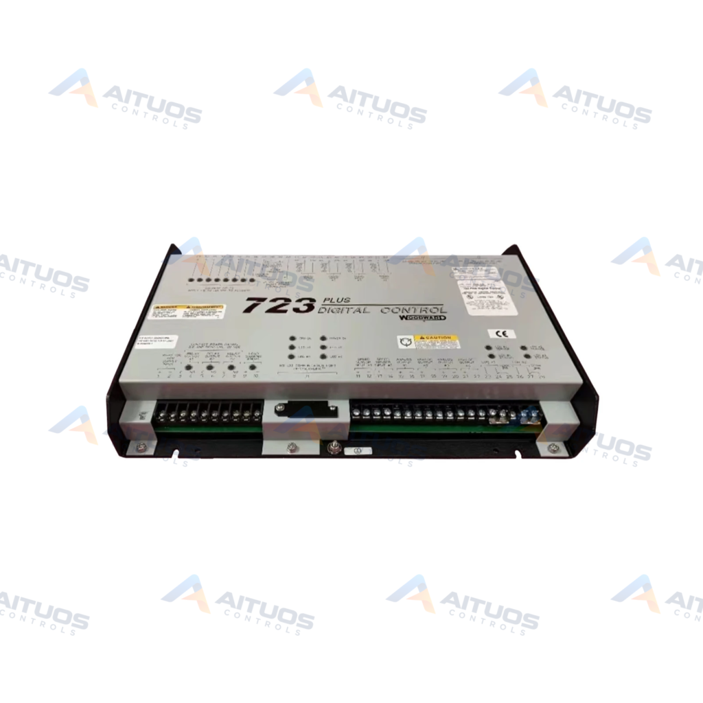
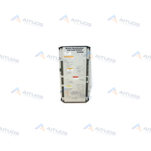
The Woodward 9906-619 is a low-voltage 723PLUS Digital Control hardware platform. This unit is a hardware-only build and contains no pre-loaded application software. It operates on an input supply range of 18 to 40 VDC. Nominal supply ratings are 24 VDC or 32 VDC with 40 watts power consumption.
The hardware is housed in a sheet metal chassis with three 9-pin D-sub connectors. Field connections wire into three onboard terminal strips. Two dedicated speed sensing channels accept magnetic pickups or proximity switches. Internal non-volatile EEPROM memory retains all configured operating parameters during power shutdowns.
TECHNICAL DATA
Technical Specifications
| Parameter | Specification |
|---|
| Exact variant | Low-voltage, hardware-only control |
|---|
| Supply voltage | 18–40 VDC; 24 or 32 VDC nominal |
|---|
| Consumption | 40 W nominal |
|---|
| Inrush current | 7 A for 0.1 ms |
|---|
| Speed inputs | 2 |
|---|
| Speed input voltage | 1.0–50.0 Vrms |
|---|
| MPU frequency | 400 Hz–15 kHz |
|---|
| Proximity frequency | 30 Hz–15 kHz |
|---|
| Speed input impedance | 10 kohm ±15% |
|---|
| Discrete inputs | 8; 24 VDC/10 mA nominal, 18–40 VDC range |
|---|
| Discrete response | 10 ms ±15%; 2.3 kohm impedance |
|---|
| Analog inputs | 4; ±5 VDC or 0–20 mA |
|---|
| Analog meter outputs | 2; 0–1 mA or 4–20 mA, 600 ohm maximum load |
|---|
| Actuator outputs | 2; 0–20 mA into 600 ohm or 0–200 mA into 70 ohm |
|---|
| Relay outputs | 3; 2.0 A resistive at 28 VDC or 0.5 A at 125 VDC |
|---|
| Environment | Operating -40 to +70 °C; storage -55 to +105 °C; 95% RH |
|---|
TECHNICAL INFORMATION
Features
- Hardware-only low-voltage platform for custom prime mover management control.
- Two speed sensor inputs accept magnetic pickups or proximity switches.
- Dual LON channels support LonTalk communications and LinkNet nodes.
- Onboard EEPROM memory preserves setpoints during power interruption.
- Eight discrete inputs and three discrete relay outputs handle logic switching.
- Two configurable actuator output channels support 0–20 mA or 0–200 mA drives.
TECHNICAL INFORMATION
Applications
- Load-sharing and droop parallel generator management systems.
- Prime mover speed regulation using magnetic pickup or proximity sensor inputs.
- Marine propulsion and auxiliary generator systems with marine classification rules.
- Mechanical drive applications requiring custom programmed governor control.
TECHNICAL INFORMATION
Connections / Interfaces
- Three terminal strips provide field wiring connection points.
- Three 9-pin subminiature D connectors include programmer port J1.
- Two LON channels interface with Woodward LinkNet distributed nodes.
- Chassis ground screw connects directly to earth ground.
TECHNICAL INFORMATION
Installation Guidelines
- Follow North American Class I, Division 2 wiring methods.
- Field wiring must be suitable for at least 75 °C if ambient exceeds 50 °C.
- Installation requires a fixed wiring configuration.
- Do not connect more than one main power supply to one protective breaker.
- Connect the chassis ground screw directly to earth ground.
TECHNICAL INFORMATION
Configuration Guidelines
- Plug Hand Held Programmer 9907-205 into serial port J1 for adjustments.
- Service, Configuration, and Hand Held Programmer menus are accessible for user tuning.
- Press the SAVE key to store modified setpoints into EEPROM memory.
- Use RABBIT UP and RABBIT DOWN keys for faster setpoint adjustment rates.
TECHNICAL INFORMATION
Compatibility
- Operates with Woodward Hand Held Programmer part number 9907-205.
- Compatible with Woodward Digital Synchronizer and Load Control units.
- Works with SPM-A synchronizers and Real Power Sensors.
- Supports LinkNet distributed input and output expansion nodes.
TECHNICAL INFORMATION
Lifecycle / Replacement Information
- Model 9906-619 is a low-voltage base hardware model without software.
- High-voltage installations require alternate hardware model 9906-620.
- Low-voltage applications needing actuator filtering use hardware model 9906-700.
TECHNICAL INFORMATION
Compliance and Certifications
- CSA Certified 2244634
- CE Compliant
- American Bureau of Shipping (ABS) 2007 Steel Vessel Rules
- Bureau Veritas (BV) Environmental Category EC Code 33
- Det Norske Veritas (DNV) Temperature Class B, Vibration Class B
- Germanischer Lloyd (GL) Environmental Category C, EMC2
- Lloyd's Register (LR) Environmental Categories ENV1, ENV2, ENV3
- Nippon Kaiji Kyokai (NKK) Rules Ch. 1, Part 7
- Registro Italiano Navale (RINA) Part C Machinery and Systems
TECHNICAL RESOURCES
Documentation
COMPATIBILITY
Compatibility & Replacement
COMPATIBLE MODELSOperates with Woodward Hand Held Programmer part number 9907-205. Compatible with Woodward Digital Synchronizer and Load Control units. Works with SPM-A synchronizers and Real Power Sensors. Supports LinkNet distributed input and output expansion nodes.
Verify compatibility against the exact Part Number, revision and manufacturer documentation before ordering.
PART VERIFICATION
Before You Order
Industrial automation parts can share similar model names, suffixes and revisions. Confirm the complete manufacturer Part Number before purchase.
01Check Part NumberMatch the complete ordering code on the existing unit.
02Confirm RevisionCheck suffix, hardware or firmware when applicable.
03Send a Label PhotoWe can review a clear label photo when identification is uncertain.
ORDERING PROCESS
From RFQ to Dispatch
1Submit Part Number2Verify Product Identity3Confirm Stock & Condition4Issue Quotation5Dispatch & Tracking
PRODUCT FAQ
Frequently Asked Questions
Does the Woodward 9906-619 include pre-loaded application software?
No. The 9906-619 is a hardware-only unit. It requires application-specific software loaded for operation.
What input power does the 9906-619 require?
The unit operates on an external supply of 18 to 40 VDC. Nominal ratings are 24 or 32 VDC.
Which speed sensors work with this control hardware?
The control accepts magnetic pickups from 400 Hz to 15 kHz. It also accepts proximity switches from 30 Hz to 15 kHz.
How are setpoint changes saved during shutdown?
Press the SAVE key on the programmer. All setpoints are saved to non-volatile EEPROM memory.