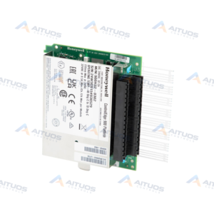
PRODUCT INFORMATION
Product Overview
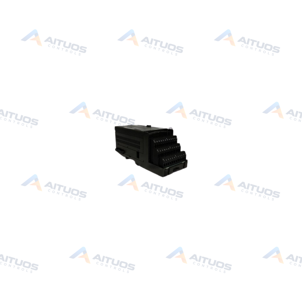
The General Electric IC200ALG262 is an analog Input Module belonging to the VersaMax series. This unit interfaces eight analog current inputs arranged in a single group. The module draws operating power directly from the backplane without an external power supply. Maximum backplane current draw is 200 mA from the 5 VDC bus voltage. An onboard OK LED provides visual indication of backplane power operation. An integrated analog-to-digital converter circuit delivers a conversion resolution of 15 bits.
Supported current input ranges include nominal 0 to 20 mA and 4 to 20 mA. Field wiring accommodates differential current connections with 100 Ohms input impedance. The update rate across all channels is 7.5 milliseconds. Digital resolution measures 0.5 µA for 4 to 20 mA and 0.625 µA for 0 to 20 mA. Built-in diagnostics detect loss of internal power. The module also detects open-wire conditions when configured for 4 to 20 mA operation.
TECHNICAL DATA
Technical Specifications
| Parameter | Specification |
|---|
| Weight | 0.56 lbs (0.26 kg) |
|---|
| Number of Inputs | 8 |
|---|
| Product Description | 4-Point Analog current input module |
|---|
| Module Type | Analog |
|---|
| Wiring configuration | Differential |
|---|
| Converter Resolution | 15 Bits |
|---|
| Input signal, nominal | 0-20 mA; 4-20 mA |
|---|
| Input Type | Single-Ended |
|---|
| Analog resolution | 15 bits |
|---|
| Update Rate | 7.5 milliseconds |
|---|
| Digital resolution | 0.5 µA for 4-20 mA; 0.625 µA for 0-20 mA |
|---|
| Current Range | 0 to 20 mA or 4 to 20 mA |
|---|
| Common mode range | -10 V to +10 V |
|---|
| Common mode rejection | 70 db |
|---|
| Input impedance | 100 Ohms |
|---|
| Input signal selection | No terminal jumper installed: 4-20 mA With Jumper installed: 0-20 mA |
|---|
| Current Draw | 200 mA, maximum |
|---|
| Input grouping | Single group |
|---|
| Diagnostics | Loss of user side power; Open wire detection for 4-20 mA |
|---|
TECHNICAL INFORMATION
Features
- Provides eight analog current input channels organized in one group.
- Utilizes a 15-bit analog-to-digital converter circuit.
- Maintains a channel update rate of 7.5 milliseconds.
- Detects open-wire conditions during 4 to 20 mA operation.
- Monitors and flags internal module power loss.
- Draws operating current directly from the 5 VDC backplane bus.
TECHNICAL INFORMATION
Applications
- Interfacing pressure, level, flow, temperature, turbidity, and viscosity transmitters.
- Monitoring speed feedback signals from variable frequency drives.
- Monitoring position feedback signals from rotary and linear measurement devices.
- Transmitting data to locally mounted panel meters for remote display implementation.
TECHNICAL INFORMATION
Connections / Interfaces
- Supports differential current wiring configurations across all eight channels.
- Requires shielded twisted pair cables for field analog wiring.
- Connects shield wiring to ground at the source device or at the I/O module.
- Includes an OK LED to display backplane power supply status.
TECHNICAL INFORMATION
Installation Guidelines
- Mount the module onto a compatible VersaMax carrier or base.
- Connect cable shields to ground at the transmitter device when possible.
- Verify the OK LED turns on when power is applied.
TECHNICAL INFORMATION
Configuration Guidelines
- Leave terminal jumpers uninstalled to select the default 4 to 20 mA range.
- Install designated terminal jumpers to set the 0 to 20 mA range.
- Configure module parameters using VersaPro software version 2.0 or higher.
TECHNICAL INFORMATION
Compatibility
- Operates with VersaMax PLC CPU firmware version 2.10 or higher.
- Communicates with VersaMax Ethernet Network Interface Units running firmware 1.10 or higher.
- Operates with VersaMax DeviceNet, Profibus, and Genius Network Interface Units.
TECHNICAL INFORMATION
Lifecycle / Replacement Information
- Emerson Automation currently manufactures the VersaMax product series.
COMPATIBILITY
Compatibility & Replacement
COMPATIBLE MODELSOperates with VersaMax PLC CPU firmware version 2.10 or higher. Communicates with VersaMax Ethernet Network Interface Units running firmware 1.10 or higher. Operates with VersaMax DeviceNet, Profibus, and Genius Network Interface Units.
Verify compatibility against the exact Part Number, revision and manufacturer documentation before ordering.
PART VERIFICATION
Before You Order
Industrial automation parts can share similar model names, suffixes and revisions. Confirm the complete manufacturer Part Number before purchase.
01Check Part NumberMatch the complete ordering code on the existing unit.
02Confirm RevisionCheck suffix, hardware or firmware when applicable.
03Send a Label PhotoWe can review a clear label photo when identification is uncertain.
ORDERING PROCESS
From RFQ to Dispatch
1Submit Part Number2Verify Product Identity3Confirm Stock & Condition4Issue Quotation5Dispatch & Tracking
PRODUCT FAQ
Frequently Asked Questions
What input current ranges are supported by the IC200ALG262?
The module accepts nominal input ranges of 0 to 20 mA and 4 to 20 mA.
How do you select the input signal range on the IC200ALG262?
Install a jumper for 0 to 20 mA. Omitting the jumper defaults channels to 4 to 20 mA.
What internal diagnostic functions does the IC200ALG262 provide?
The module detects loss of internal user-side power. It also provides open-wire detection in 4 to 20 mA mode.
Does the IC200ALG262 require an external power supply?
No. The module receives its operating power directly from the 5 VDC backplane bus.