PRODUCT INFORMATION
Product Overview
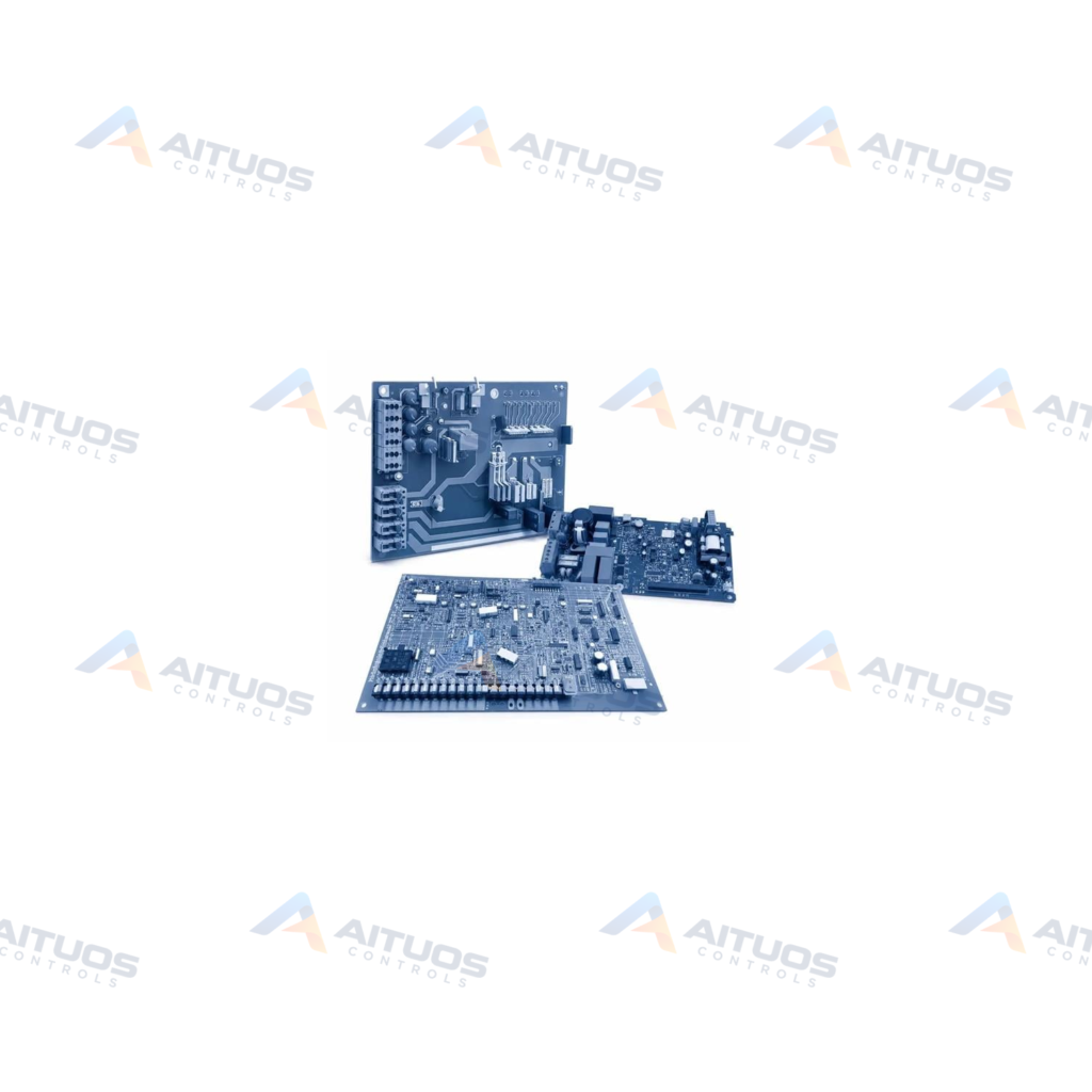
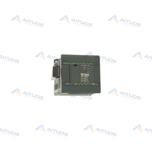
The General Electric IS200JPDEG1A is a DC Battery Distribution Board designed for Mark VI and Mark VIe turbine control systems. It distributes direct current power from a station battery or power supply to connected system loads. These target loads typically include Mark VIe series terminal board assemblies. The IS200JPDEG1A represents an A-rated functional product revision of the base IS200JPDEG1 circuit board.
The board mounts directly inside a power distribution module enclosure using a dedicated metal mounting bracket. This mounting bracket includes a factory piercing to provide a grounding output terminal connection. The assembly features two 50-pin diagnostic connectors, designated P1 and P2, located at the circuit board edges. These ports handle feedback signal transmission and reception with an associated PPDA input and output pack.
TECHNICAL DATA
Technical Specifications
| Parameter | Specification |
|---|
| PCB Coating | Normal Coating |
|---|
TECHNICAL INFORMATION
Features
- Distributes direct current power from batteries or power supplies to Mark VIe terminal boards.
- Equipped with two fifty-pin diagnostic pin connectors labeled P1 and P2.
- Communicates feedback signals directly with the turbine control system PPDA input/output pack.
- Includes two nine-pin Mate-n-lock connectors designated for power supply input wiring.
- Features an integrated DC circuit breaker and a 30A input filter for battery applications.
- Constructed with customizable onboard switches designed for maintenance procedures.
- Protected with a standard normal printed circuit board coating across components.
TECHNICAL INFORMATION
Applications
- Mark VIe turbine control system power distribution assemblies.
- Power distribution modules requiring battery and auxiliary power branching.
- Turbine control system terminal board supply feeds.
TECHNICAL INFORMATION
Connections / Interfaces
- Two 50-pin diagnostic connectors labeled P1 and P2 interface with the PPDA I/O pack.
- Two 9-pin Mate-n-lock connectors receive primary power supply input.
- A dedicated grounding output terminal connects through the pierced sheet metal bracket.
TECHNICAL INFORMATION
Installation Guidelines
- Mount the board within a power distribution module assembly using the supplied metal bracket.
- Secure the unit using the four factory-drilled installation holes on the bracket.
- Ensure the pierced chassis ground connection on the sheet metal bracket is firmly grounded.
TECHNICAL INFORMATION
Configuration Guidelines
- Configure the onboard maintenance switches according to system operational requirements.
- Verify feedback communication with the PPDA input/output pack during system commissioning.
TECHNICAL INFORMATION
Compatibility
- Compatible with General Electric Mark VI and Mark VIe modular power distribution architectures.
- Interfaces directly with the GE PPDA input/output pack for diagnostic signal tracking.
- Delivers operational power to Mark VIe series terminal board products.
COMPATIBILITY
Compatibility & Replacement
COMPATIBLE MODELSCompatible with General Electric Mark VI and Mark VIe modular power distribution architectures. Interfaces directly with the GE PPDA input/output pack for diagnostic signal tracking. Delivers operational power to Mark VIe series terminal board products.
Verify compatibility against the exact Part Number, revision and manufacturer documentation before ordering.
PART VERIFICATION
Before You Order
Industrial automation parts can share similar model names, suffixes and revisions. Confirm the complete manufacturer Part Number before purchase.
01Check Part NumberMatch the complete ordering code on the existing unit.
02Confirm RevisionCheck suffix, hardware or firmware when applicable.
03Send a Label PhotoWe can review a clear label photo when identification is uncertain.
ORDERING PROCESS
From RFQ to Dispatch
1Submit Part Number2Verify Product Identity3Confirm Stock & Condition4Issue Quotation5Dispatch & Tracking
PRODUCT FAQ
Frequently Asked Questions
What is the primary function of the IS200JPDEG1A board?
It distributes direct current power from a battery or power supply to Mark VIe system loads.
How does the IS200JPDEG1A communicate diagnostic feedback?
Two 50-pin connectors, designated P1 and P2, transmit feedback signals to a PPDA I/O pack.
What hardware protection is integrated on the IS200JPDEG1A?
It includes a DC circuit breaker, a 30A input filter, and normal PCB protective coating.
How is the IS200JPDEG1A mounted in the cabinet?
The board mounts in a PDM drive assembly using a pierced metal bracket with four holes.