PRODUCT INFORMATION
Product Overview
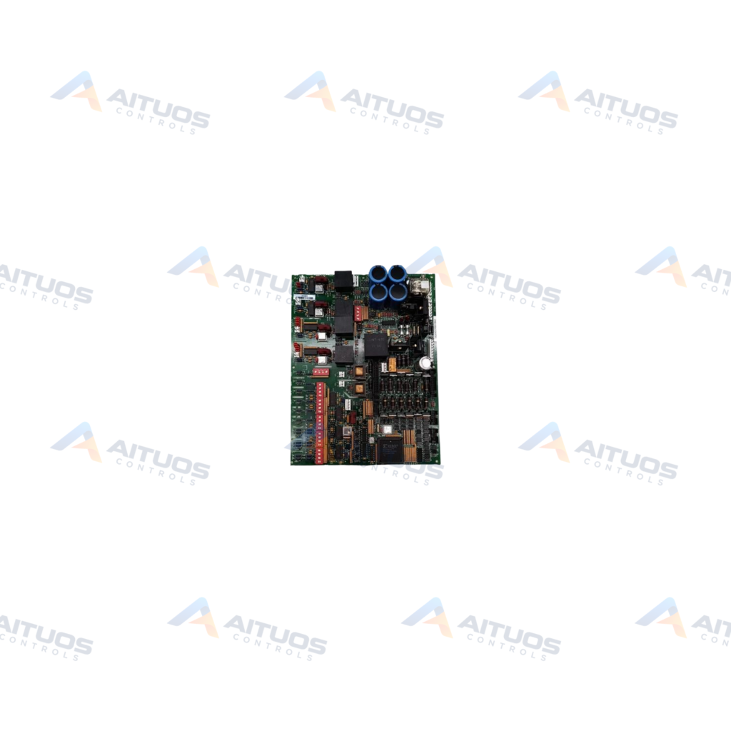
The General Electric DS200DCFBG1BNC is a Mark V power supply board. This board operates within the Speedtronic Mark V control system for gas, steam, and wind turbine assemblies. It delivers control level operating power and energizes enclosure cooling fans across supported turbine drive cabinets. The unit supports compatibility with General Electric FC2000, AC2000, DC2000, ME2000, and CB2000 drive lineups.
The board accepts an input voltage range from 38 to 115 VAC. Internal architecture incorporates five operational circuits for power distribution and line monitoring. These comprise a driver circuit, control level supply, motor field circuit, AC monitoring, and DC monitoring. Hardware protection includes three onboard fuses monitored by integrated LED and neon indicator lamps.
TECHNICAL DATA
Technical Specifications
| Parameter | Specification |
|---|
| Instruction Manual | GEI-100028 |
|---|
| PCB Coating | Normal Coating |
|---|
| Weight | 2 lb |
|---|
TECHNICAL INFORMATION
Features
- Accepts an input voltage range between 38 and 115 VAC.
- Includes five internal circuits for driving, control power, motor fields, and AC or DC monitoring.
- Equipped with three protective fuses alongside integrated LED and neon indicators.
- Provides five dedicated voltage test points including P5, DCOM, P15, N15, and ACCT.
- Features configurable jumpers and seven DIP switches for tailored operation.
TECHNICAL INFORMATION
Applications
- Speedtronic Mark V automated drive assemblies managing gas, steam, or wind turbines.
- General Electric FC2000, AC2000, and DC2000 industrial drive systems.
- General Electric ME2000 and CB2000 cabinet assemblies requiring control level power.
TECHNICAL INFORMATION
Connections / Interfaces
- Five test points provide access to P5, DCOM, P15, N15, and ACCT signal lines.
- Onboard DIP switches and hardware jumpers allow operational field adjustments.
TECHNICAL INFORMATION
Installation Guidelines
- Treat the assembly as static sensitive and apply electrostatic discharge protection during handling.
- Surface voltages may present electrical hazards during and immediately after operation.
- Follow installation and wiring procedures detailed in General Electric instruction manual GEI-100028.
TECHNICAL INFORMATION
Configuration Guidelines
- Seven onboard DIP switches configure operational modes for connected drive hardware.
- Hardware jumpers allow scaling selection and system tuning per technical specifications.
TECHNICAL INFORMATION
Compatibility
- Compatible with General Electric Speedtronic Mark V turbine control systems.
- Interfaces with GE FC2000, AC2000, DC2000, ME2000, and CB2000 drives.
TECHNICAL INFORMATION
Lifecycle / Replacement Information
- The DS200DCFBG1BNC features three product revisions beyond the parent DS200DCFBG1 power supply board.
COMPATIBILITY
Compatibility & Replacement
COMPATIBLE MODELSCompatible with General Electric Speedtronic Mark V turbine control systems. Interfaces with GE FC2000, AC2000, DC2000, ME2000, and CB2000 drives.
Verify compatibility against the exact Part Number, revision and manufacturer documentation before ordering.
PART VERIFICATION
Before You Order
Industrial automation parts can share similar model names, suffixes and revisions. Confirm the complete manufacturer Part Number before purchase.
01Check Part NumberMatch the complete ordering code on the existing unit.
02Confirm RevisionCheck suffix, hardware or firmware when applicable.
03Send a Label PhotoWe can review a clear label photo when identification is uncertain.
ORDERING PROCESS
From RFQ to Dispatch
1Submit Part Number2Verify Product Identity3Confirm Stock & Condition4Issue Quotation5Dispatch & Tracking
PRODUCT FAQ
Frequently Asked Questions
What input voltage does the GE DS200DCFBG1BNC board require?
The board accepts input voltage levels ranging from 38 to 115 VAC.
Which GE drive systems support the DS200DCFBG1BNC power supply?
The board is compatible with GE FC2000, AC2000, DC2000, ME2000, and CB2000 drive series.
How can technicians verify voltage levels on the DS200DCFBG1BNC?
Technicians can monitor board operation using five test points labeled P5, DCOM, P15, N15, and ACCT.