PRODUCT INFORMATION
Product Overview
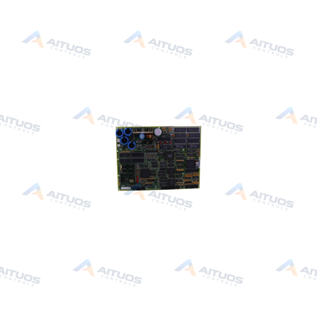
The General Electric DS200DMCBG1A is a DOS DUP Processor Board for Mark V control systems. It operates in Speedtronic systems managing compatible gas, steam, and wind turbine automated drive assemblies. The board processes operational control signals within the Mark V system architecture. It features a normal PCB coating style and belongs to the Mark V group one product line. The functional acronym for this printed circuit board is DMCB.
Hardware on the board includes three 26-pin connectors, one 40-pin connector, and 19 jumpers. An onboard pushbutton enables qualified servicers to restart board operations without restarting the drive. Pressing this reset button for three seconds clears active signals and restarts normal operations. Visual diagnostics include two red LED indicators designated CR1 and CR12 in one board corner. Two onboard fuses provide circuit protection and must be replaced only with matching ratings.
TECHNICAL DATA
Technical Specifications
| Parameter | Specification |
|---|
| Functional Abbreviation | DMCB |
|---|
| PCB Coating Style | Normal Coating |
|---|
| 1st Functional Revision | A |
|---|
TECHNICAL INFORMATION
Features
- Three 26-pin connectors and one 40-pin connector
- Nineteen onboard jumpers for hardware configuration
- Manual reset pushbutton allowing board restart without restarting the drive
- Two red diagnostic LEDs designated CR1 and CR12
- Two onboard protective fuses
- Group 1 normal PCB protective coating style
- First functional revision level A hardware design
TECHNICAL INFORMATION
Applications
- General Electric Mark V Speedtronic turbine control systems
- Gas turbine automated drive and control management
- Steam turbine automated control systems
- Wind turbine automated drive assemblies
TECHNICAL INFORMATION
Connections / Interfaces
- Three 26-pin connectors
- One 40-pin connector
- Nineteen hardware jumpers
TECHNICAL INFORMATION
Installation Guidelines
- Locate the processor board inside the Mark V cabinet.
- Attach connections securely to the three 26-pin connectors and one 40-pin connector.
- Configure all 19 jumpers according to system documentation before applying power.
TECHNICAL INFORMATION
Configuration Guidelines
- Press and hold the reset button for three seconds to clear signals and restart operations.
- Observe red diagnostic LEDs CR1 and CR12 located together in one corner of the board.
- Check the two onboard fuses and replace any blown fuse with an identical rating.
TECHNICAL INFORMATION
Compatibility
- General Electric Speedtronic Mark V turbine control assemblies
COMPATIBILITY
Compatibility & Replacement
COMPATIBLE MODELSGeneral Electric Speedtronic Mark V turbine control assemblies
Verify compatibility against the exact Part Number, revision and manufacturer documentation before ordering.
PART VERIFICATION
Before You Order
Industrial automation parts can share similar model names, suffixes and revisions. Confirm the complete manufacturer Part Number before purchase.
01Check Part NumberMatch the complete ordering code on the existing unit.
02Confirm RevisionCheck suffix, hardware or firmware when applicable.
03Send a Label PhotoWe can review a clear label photo when identification is uncertain.
ORDERING PROCESS
From RFQ to Dispatch
1Submit Part Number2Verify Product Identity3Confirm Stock & Condition4Issue Quotation5Dispatch & Tracking
PRODUCT FAQ
Frequently Asked Questions
What is the primary function of the GE DS200DMCBG1A board?
The DS200DMCBG1A serves as a DOS DUP processor board for General Electric Mark V turbine control systems. It operates in compatible gas, steam, and wind turbine automated drive assemblies.
How do you reset the DS200DMCBG1A processor board?
Press the onboard reset button for three seconds and then release it. This clears signals and restarts board operations without restarting the drive.
What onboard connectors and jumpers are present on the DS200DMCBG1A?
The board contains three 26-pin connectors, one 40-pin connector, and 19 jumpers for system configuration.
What visual diagnostic indicators does the DS200DMCBG1A provide?
The board includes two red LEDs designated CR1 and CR12 in one corner. Original documentation details their diagnostic status meanings.