PRODUCT INFORMATION
Product Overview
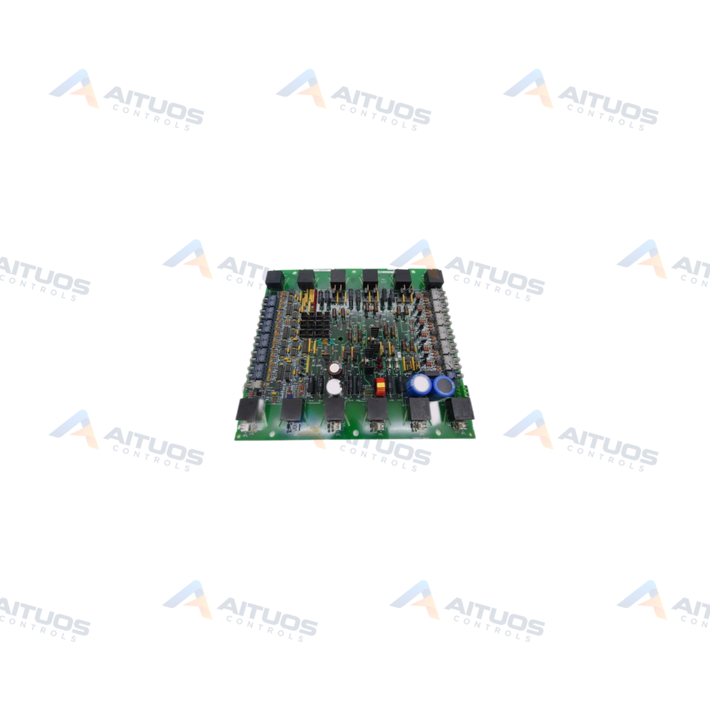
The General Electric DS200FCRRG1AKD is a Firing Control Circuit Board designed for the Mark V control system. This printed circuit board features one terminal block engineered for ninety-five signal wires. It also includes ten two-pin connectors and two ribbon cable interfaces. A programmable logic device coordinates on-board logic operations for drive firing routines. Standardized voltage-limiting components such as capacitors, resistors, and diodes populate the assembly.
The board carries surface-printed identifiers for its ten two-pin connectors, ending with the suffix PL. Typical printed connector designators include 1PL, 5PL, 12PL, and 15PL. Proper cable positioning prevents operational errors during drive start-up sequences. The physical hardware incorporates a three-fold revision history altering dimensions and component configurations. Maintenance technicians must handle the board using standard static-sensitive handling precautions.
TECHNICAL DATA
Technical Specifications
| Parameter | Specification |
|---|
| PCB Coating | Normal Coating |
|---|
| Assembly Type | Normal Assembly |
|---|
TECHNICAL INFORMATION
Features
- Features a single large terminal block accommodating ninety-five signal wires.
- Contains ten two-pin connectors designated sequentially with a PL suffix.
- Includes two ribbon cable connection points for internal data routing.
- Integrates an on-board programmable logic device for timing control.
- Built with normal assembly specifications and normal board coating.
TECHNICAL INFORMATION
Connections / Interfaces
- One terminal block supporting up to 95 signal wire connections.
- Ten 2-pin connectors labeled with identifiers including 1PL, 5PL, 12PL, and 15PL.
- Two multi-pin ribbon cable interfaces.
TECHNICAL INFORMATION
Installation Guidelines
- Record all cable connection points before disconnecting any wiring from the board.
- Verify two-pin cable positions carefully to prevent faults during subsequent drive startup.
- Use a narrow flat-blade screwdriver to loosen terminal retention screws.
- Strip approximately 0.5 inches of insulation from wire ends before terminal insertion.
- Insert all bare wire completely into the terminal clamp to ensure electrical contact.
- Avoid stripping under 0.5 inches, as insufficient bare copper prevents terminal connectivity.
PART VERIFICATION
Before You Order
Industrial automation parts can share similar model names, suffixes and revisions. Confirm the complete manufacturer Part Number before purchase.
01Check Part NumberMatch the complete ordering code on the existing unit.
02Confirm RevisionCheck suffix, hardware or firmware when applicable.
03Send a Label PhotoWe can review a clear label photo when identification is uncertain.
ORDERING PROCESS
From RFQ to Dispatch
1Submit Part Number2Verify Product Identity3Confirm Stock & Condition4Issue Quotation5Dispatch & Tracking
PRODUCT FAQ
Frequently Asked Questions
What is the function of the General Electric DS200FCRRG1AKD board?
It operates as a firing control circuit board within General Electric Mark V drive and turbine systems.
How should signal wires be prepared for the DS200FCRRG1AKD terminal block?
Strip approximately 0.5 inches of insulation from the wire end and insert all bare conductor into the terminal.
Why must 2-pin cable connections be documented before removal on the DS200FCRRG1AKD?
Mismatched 2-pin cable connections may not show errors until drive start-up is attempted.