PRODUCT INFORMATION
Product Overview
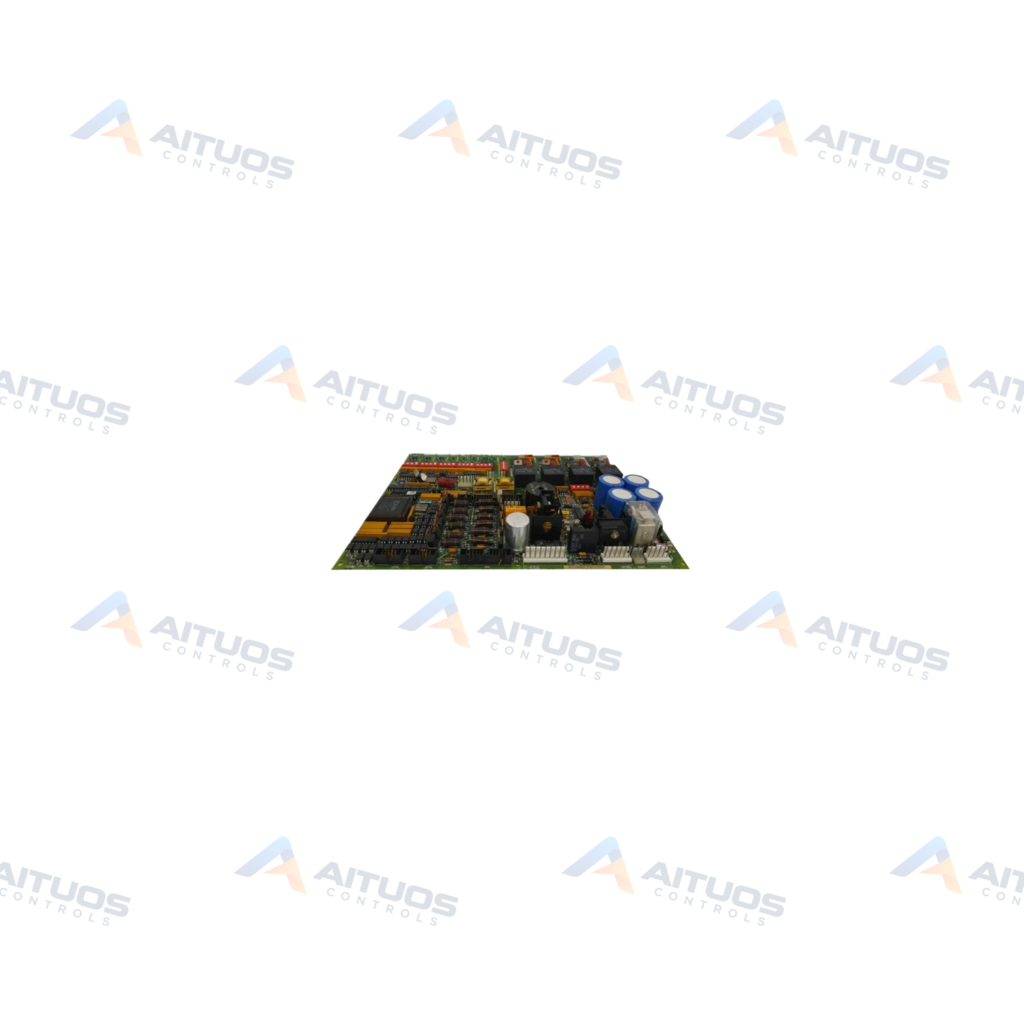
The General Electric DS200DCFBG1B is a Mark V power supply board. This board delivers control-level operating power and enclosure fan power across supported drive systems. Compatible turbine drive platforms include AC2000, CB2000, DC2000, FC2000, ME2000, and EX2000 systems. The EX2000 excitation system utilizes this board differently from other listed drive architectures.
The board interfaces with SDCC and LDCC control cards to communicate motor voltage feedback signals. An internal voltage-controlled oscillator converts measured input voltages into frequency signals sent over connector 1PL. DIP switch SW6 provides active scaling and modification for motor voltage feedback. Onboard amplifier circuits further process these signals for the main control cards.
TECHNICAL DATA
Technical Specifications
| Parameter | Specification |
|---|
| Instruction Manual | GEI-100028 |
|---|
| Weight | 1.3 lbs |
|---|
| Board Revision | B |
|---|
| Configurable Jumpers | 12 on-board Jumpers (13 for revision BKC or later) |
|---|
| DIP Switches | 7 DIP switches for selection of application options |
|---|
| LED and Neon Light Indicators | Two Red LEDs (CR51 and CR55) and a single neon light (LT1) |
|---|
| Testpoints | Five testpoints for voltage signals, board common, and ACCT signal status |
|---|
| Fuses | Qty 3 fuses at FU1, FU2, and FU3 are used for power supply protection |
|---|
| Connectors | Qty 18 plug connectors and Qty 9 stab connectors |
|---|
TECHNICAL INFORMATION
Features
- Includes twelve hardware jumpers and seven DIP switches for application-specific configuration.
- Provides onboard driver circuits for Silicon Controlled Rectifier generators.
- Monitors AC line current, armature current, armature voltage, and motor field parameters.
- Contains three integrated protective fuses designated FU1, FU2, and FU3.
- Provides visual diagnostics via two red LED indicators and one neon status light.
TECHNICAL INFORMATION
Applications
- General Electric Mark V turbine drive systems.
- AC2000, CB2000, DC2000, FC2000, and ME2000 drives.
- EX2000 excitation control architectures.
TECHNICAL INFORMATION
Connections / Interfaces
- Features eighteen plug-style connectors for system cabling.
- Includes nine stab-style connectors for internal drive interconnections.
- Connector 1PL routes frequency signals directly to SDCC or LDCC control boards.
TECHNICAL INFORMATION
Installation Guidelines
- Use the five onboard test points to monitor voltage signals and board common.
- Test points also provide verification of ACCT signal statuses during servicing.
- Red LED CR51 indicates DC regulator status for fuse FU2.
- Red LED CR55 displays DC regulator status for fuse FU3.
- Neon lamp LT1 displays operating status for AC line fuse FU1.
TECHNICAL INFORMATION
Configuration Guidelines
- Configure DIP switch SW6 to scale or modify motor voltage feedback values.
- Set the seven onboard DIP switches according to the specific drive manual GEI-100028.
- Position the twelve JP jumpers to match your system drive requirements.
TECHNICAL INFORMATION
Compatibility
- Interfaces directly with Mark V SDCC and LDCC drive control boards.
- Operates within GE AC2000, CB2000, DC2000, FC2000, ME2000, and EX2000 systems.
COMPATIBILITY
Compatibility & Replacement
COMPATIBLE MODELSInterfaces directly with Mark V SDCC and LDCC drive control boards. Operates within GE AC2000, CB2000, DC2000, FC2000, ME2000, and EX2000 systems.
Verify compatibility against the exact Part Number, revision and manufacturer documentation before ordering.
PART VERIFICATION
Before You Order
Industrial automation parts can share similar model names, suffixes and revisions. Confirm the complete manufacturer Part Number before purchase.
01Check Part NumberMatch the complete ordering code on the existing unit.
02Confirm RevisionCheck suffix, hardware or firmware when applicable.
03Send a Label PhotoWe can review a clear label photo when identification is uncertain.
ORDERING PROCESS
From RFQ to Dispatch
1Submit Part Number2Verify Product Identity3Confirm Stock & Condition4Issue Quotation5Dispatch & Tracking
PRODUCT FAQ
Frequently Asked Questions
What is the primary role of the DS200DCFBG1B power supply board?
The DS200DCFBG1B delivers control-level power and enclosure fan power. It also provides motor voltage feedback.
How does the DS200DCFBG1B communicate with drive control cards?
It converts input voltages into frequency signals using a voltage-controlled oscillator. Signals route to SDCC or LDCC boards via connector 1PL.
What diagnostic indicators are present on the DS200DCFBG1B?
The board includes two red LEDs and one neon lamp. Red LEDs CR51 and CR55 monitor DC regulator fuses. Neon light LT1 monitors the AC line fuse.
How is motor voltage feedback modified on the DS200DCFBG1B?
DIP switch SW6 allows technicians to actively scale and modify motor voltage feedback. Onboard amplifier circuits condition the signals.