PRODUCT INFORMATION
Product Overview
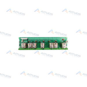
General Electric IS200SCNVG1ADC Interface Board serves as an SCR-Diode converter interface within the Speedtronic Mark VI system. The board functions inside stand-alone 1000 A and 1800 A Innovation Series SCR-Diode Converters as a bridge interface. It operates with 6-pulse sources driving three SCRs per board and cannot drive parallel SCRs directly.
This printed circuit board installs into Slot 6 of an Innovation Series rack. It connects directly to connector J15 on the CABP board. System control interfaces communicate via a 128-pin P1 backplane connector. Onboard circuits monitor line voltages, link voltages, and current feedback across turbine drive assemblies.
TECHNICAL DATA
Technical Specifications
| Parameter | Specification |
|---|
| Functional Acronym/Abbreviation | SCVN |
|---|
| Product Description | SCR-Diode Converter Interface Board |
|---|
| Used With | Innovation Series |
|---|
| Weight | 10 ounces |
|---|
TECHNICAL INFORMATION
Features
- Operates as a control-to-bridge interface in 1000 A and 1800 A converters.
- Drives three SCRs per board for 6-pulse power source configurations.
- Integrates a 128-pin P1 backplane connector for system communication.
- Features six plug connectors for gate drivers, DC links, and current shunts.
- Includes three SCR gate drivers and three input current sensing circuits.
- Provides two line-to-line voltage feedback channels and one DC link voltage feedback channel.
- Contains one dynamic braking IGBT gate driver and dynamic braking IGBT VCE feedback.
- Includes an add-only memory device containing identification and revision data accessed via the BRDID line.
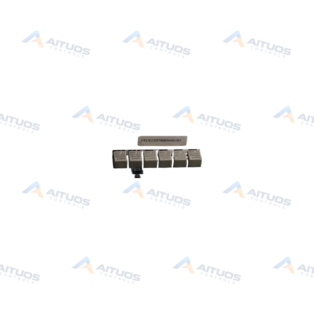
- Contains four onboard transformers to provide secondary power distribution.
TECHNICAL INFORMATION
Applications
- General Electric Mark VI Speedtronic control systems.
- Stand-alone 1000 A and 1800 A Innovation Series SCR-Diode Converters.
- Automated drive assemblies for gas, steam, and wind turbine applications.
TECHNICAL INFORMATION
Connections / Interfaces
- P1 backplane connector with 128 pins for power and system interfacing.
- Direct connection to connector J15 of the CABP board.
- Six plug connectors interfacing with current shunts, DC links, and gate drivers.
- BRDID data line connection through P1 to read electronic ID and revision data.
TECHNICAL INFORMATION
Installation Guidelines
- Mount the board securely into Slot 6 of the Innovation rack.
- Engage the 128-pin P1 backplane connector firmly with the mating rack connector.
- Verify proper seating with connector J15 on the CABP board.
- Do not probe the four development test points due to high-voltage hazards.
TECHNICAL INFORMATION
Configuration Guidelines
- The board contains no adjustable jumpers, configurable fuses, or LED status indicators.
- Do not configure the board to drive parallel SCR devices from a single unit.
- Access board identification and hardware revision details over the BRDID line via connector P1.
TECHNICAL INFORMATION
Compatibility
- General Electric Mark VI Speedtronic turbine control platforms.
- Innovation Series 1000 A and 1800 A SCR-Diode Converters.
- Innovation Series CABP backplane connector J15.
COMPATIBILITY
Compatibility & Replacement
COMPATIBLE MODELSGeneral Electric Mark VI Speedtronic turbine control platforms. Innovation Series 1000 A and 1800 A SCR-Diode Converters. Innovation Series CABP backplane connector J15.
Verify compatibility against the exact Part Number, revision and manufacturer documentation before ordering.
PART VERIFICATION
Before You Order
Industrial automation parts can share similar model names, suffixes and revisions. Confirm the complete manufacturer Part Number before purchase.
01Check Part NumberMatch the complete ordering code on the existing unit.
02Confirm RevisionCheck suffix, hardware or firmware when applicable.
03Send a Label PhotoWe can review a clear label photo when identification is uncertain.
ORDERING PROCESS
From RFQ to Dispatch
1Submit Part Number2Verify Product Identity3Confirm Stock & Condition4Issue Quotation5Dispatch & Tracking
PRODUCT FAQ
Frequently Asked Questions
What is the primary function of the IS200SCNVG1ADC board?
The board operates as an SCR-Diode converter interface in 1000 A and 1800 A Innovation Series converters.
Which rack slot is required for installing the IS200SCNVG1ADC?
The IS200SCNVG1ADC is designed to mount specifically in Slot 6 of the Innovation rack.
Can the IS200SCNVG1ADC drive parallel SCRs?
No. The board cannot drive parallel SCRs from the same board, but supports three SCRs for 6-pulse sources.
What power connections supply the IS200SCNVG1ADC?
The board receives Vdc power through the P1 connector and secondary power through four onboard transformers.