PRODUCT INFORMATION
Product Overview
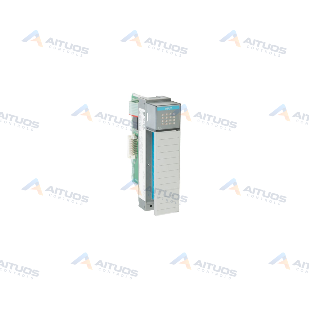
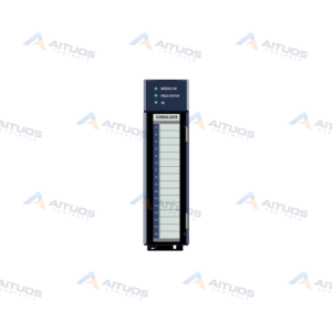
The Allen-Bradley 1746-IG16 is a Digital DC Input Module designed for the SLC 500 series platform. It provides 16 current sourcing transistor-transistor logic input points with a single fused common. The operating voltage range spans from 4.5 to 5.5 volts DC. Maximum peak-to-peak ripple voltage is 50 millivolts. It interfaces directly with TTL signal levels and BCD instrumentation devices.
This input module operates using inverse logic. Low voltage levels from -0.2 to 0.8 volts DC register as an ON state. High voltage levels between 2.0 and 5.5 volts DC register as an OFF state. Backplane current draw equals 0.14 amperes at 5 volts DC. Total module power dissipation is 1 watt, with 0.02 watts dissipated per point.
TECHNICAL DATA
Technical Specifications
| Parameter | Specification |
|---|
| Applications | TTL or BCD inputs |
|---|
| Backplane Current (5 Volts DC) | 140 milliamps |
|---|
| Category | PLCs |
|---|
| I/O Connection | 1746-HT and 1746-HCA |
|---|
| Inputs | 16 |
|---|
| Minimum Watts | 0.7 |
|---|
| Module Type | Digital DC Input Module |
|---|
| Octal Kit | 1746-RL42 |
|---|
| Removable Terminal Block | 1746-RT25B |
|---|
| Signal delay | 0.25 or 0.5 milliseconds |
|---|
| Step Response | 100 milliseconds in, 2.5 milliseconds out |
|---|
| Total Watts | 1 |
|---|
| UPC | 662468092722 |
|---|
| Voltage Range | 4.5-5.5 Volts DC Source |
|---|
| Watts Per Point | 0.02 |
|---|
| Weight | 1.50 lbs (0.68 kg) |
|---|
TECHNICAL INFORMATION
Features
- Provides 16 current-sourcing transistor-transistor logic inputs sharing one fused common.
- Operates across a DC input voltage range of 4.5 to 5.5 volts.
- Delivers signal delay performance of 0.25 milliseconds ON and 0.5 milliseconds OFF.
- Offers 1500 volts electro-optical isolation between control logic and field input terminals.
- Withstands 30G operational shock and 2.5G operational vibration from 57 to 200 Hertz.
- Meets NEMA ICS 2-230 electrical noise immunity standards.
TECHNICAL INFORMATION
Applications
- Interfacing TTL logic output ports from external electronic equipment.
- Receiving binary-coded decimal signals from process instrumentation.
TECHNICAL INFORMATION
Connections / Interfaces
- Supports I/O connection types 1746-HT and 1746-HCA.
- Uses the 1746-RT25B removable terminal block for field wiring.
- Compatible with the 1746-RL42 octal kit configuration.
TECHNICAL INFORMATION
Installation Guidelines
- Installs into any available slot of an SLC 500 chassis except slot 0.
- Slot 0 remains reserved strictly for the SLC 500 controller.
- Handle the module by the unit ends to avoid electrostatic discharge damage.
- Do not contact metallic surfaces during physical handling or chassis insertion.
- Keep DC signal wiring separated from communication lines and power wiring.
- Limit input signal wiring runs to 15 meters or 50 feet per point.
TECHNICAL INFORMATION
Configuration Guidelines
- Configure external circuits for active-low current-sourcing TTL input operation.
- Verify that input low signals remain within -0.2 to 0.8 volts DC.
- Ensure input high signals stay between 2.0 and 5.5 volts DC.
- Group similar module types together in the chassis for clean wiring and troubleshooting.
TECHNICAL INFORMATION
Compatibility
- The module installs into standard modular SLC 500 chassis.
- It mixes with other SLC 500 digital and analog I/O modules.
TECHNICAL INFORMATION
Compliance and Certifications
- UL listed and CSA certified for industrial control installations.
- Classified for UL-A196, C-UL, and CSA Class I, Division 2 hazardous environments.
- Complies with NEMA ICS 2-230 electrical noise immunity specifications.
COMPATIBILITY
Compatibility & Replacement
COMPATIBLE MODELSThe module installs into standard modular SLC 500 chassis. It mixes with other SLC 500 digital and analog I/O modules.
Verify compatibility against the exact Part Number, revision and manufacturer documentation before ordering.
PART VERIFICATION
Before You Order
Industrial automation parts can share similar model names, suffixes and revisions. Confirm the complete manufacturer Part Number before purchase.
01Check Part NumberMatch the complete ordering code on the existing unit.
02Confirm RevisionCheck suffix, hardware or firmware when applicable.
03Send a Label PhotoWe can review a clear label photo when identification is uncertain.
ORDERING PROCESS
From RFQ to Dispatch
1Submit Part Number2Verify Product Identity3Confirm Stock & Condition4Issue Quotation5Dispatch & Tracking
PRODUCT FAQ
Frequently Asked Questions
What input logic levels trigger the Allen-Bradley 1746-IG16?
The 1746-IG16 uses inverted logic where -0.2 to 0.8 VDC is ON and 2 to 5.5 VDC is OFF.
Which chassis slots accept the 1746-IG16 module?
It installs into any SLC 500 chassis slot except slot 0, which houses the processor.
What is the maximum wiring distance for 1746-IG16 inputs?
Field signal wiring should not exceed 15 meters or 50 feet per point.
Which removable terminal block works with the 1746-IG16?
The module uses the 1746-RT25B removable terminal block for field terminations.