PRODUCT INFORMATION
Product Overview
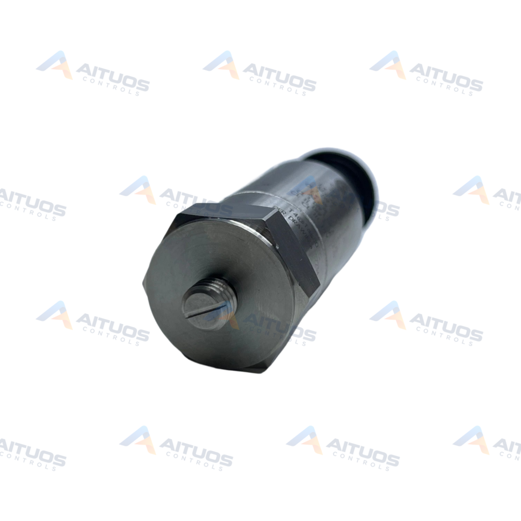
The Bently Nevada 177230-01-02-05 is a 177230 series loop-powered seismic transmitter. It integrates a ceramic shear sensing element within a hermetically sealed 316L stainless steel case. The unit provides continuous casing vibration velocity monitoring across an operating temperature range of -40 to +85 °C. Option 01 configures a peak velocity measurement range of 0 to 25.4 mm/s.
The transmitter generates a primary 4 to 20 mA loop output proportional to peak velocity. Option 02 defines the velocity bandpass frequency response from 3 Hz to 1 kHz. An auxiliary dynamic acceleration voltage output is available on connector pin C. Operating excitation requires 12 to 30 VDC loop power with current limited to 40 mA. Option 05 provides hazardous area certifications including CSA, NRTL/C, ATEX, and IECEx approvals.
TECHNICAL DATA
Technical Specifications
| Parameter | Specification |
|---|
| Main output | 4–20 mA loop proportional to velocity |
|---|
| Velocity range | 0–25.4 mm/s peak |
|---|
| Velocity frequency response | 3 Hz–1 kHz peak |
|---|
| Excitation | 12–30 VDC; current limited to 40 mA |
|---|
| Settling time | Less than 15 s to within 2% of final value |
|---|
| Dynamic output | Acceleration voltage on pin C |
|---|
| Dynamic sensitivity | 10.2 mV/(m/s²), equivalent to 100 mV/g, ±20% |
|---|
| Dynamic frequency response | 1 Hz–10 kHz, ±3 dB |
|---|
| Linearity | ±1% |
|---|
| Output bias | 2.5 ±0.1 V |
|---|
| Acceleration full scale | 147 m/s² (15 g) peak |
|---|
| Mounted resonance | Above 12 kHz |
|---|
| Transverse sensitivity | Less than 5% |
|---|
| Sensing element | Ceramic/shear |
|---|
| Operating temperature | -40 to +85 °C |
|---|
| Electrical isolation | Greater than 10^8 ohm |
|---|
| Isolation breakdown | 600 Vrms with less than 1 mA leakage |
|---|
| Sealing | Hermetically sealed; 100% RH non-submerged |
|---|
| Body | 316L stainless steel; 25.4 mm diameter × 66 mm high |
|---|
| Weight | 131 g typical |
|---|
| Connector | 3-pin MIL-C-5015 |
|---|
| Mounting | 1/4-28 UNF; 4–7 N·m |
|---|
| Approvals | Option 05 — CSA/NRTL/C and ATEX/IECEx multiple approvals |
|---|
| Instrument type | Loop-powered seismic vibration transmitter |
|---|
| Primary output | 4–20 mA proportional to velocity |
|---|
| Velocity range option 01 | 0–25.4 mm/s peak |
|---|
| Frequency option 02 | 3 Hz–1 kHz peak |
|---|
| Supply | 12–30 VDC; current limited to 40 mA |
|---|
| Mounting thread | 1/4-28 UNF |
|---|
| Approvals option 05 | CSA/NRTL/C and ATEX/IECEx |
|---|
TECHNICAL INFORMATION
Features
- Provides a 4 to 20 mA loop output proportional to velocity.
- Includes an auxiliary dynamic acceleration voltage signal on pin C.
- Utilizes a ceramic shear sensing element.
- Features a measurement range of 0 to 25.4 mm/s peak.
- Operates with a frequency response of 3 Hz to 1 kHz.
- Constructed with a hermetically sealed 316L stainless steel housing.
- Connects via a 3-pin MIL-C-5015 electrical interface.
- Certified under Option 05 for CSA, NRTL/C, ATEX, and IECEx.
TECHNICAL INFORMATION
Applications
- Continuous casing vibration monitoring.
- Direct connection to 4 to 20 mA control system loops.
TECHNICAL INFORMATION
Connections / Interfaces
- Features a top-mounted 3-pin MIL-C-5015 connector.
- Pin C supplies the dynamic acceleration output signal.
- The transmitter operates from a 12 to 30 VDC loop supply.
TECHNICAL INFORMATION
Installation Guidelines
- Mount the transmitter using a 1/4-28 UNF threaded stud.
- Tighten the mounting stud to an installation torque of 4 to 7 N·m.
- Ensure the mounting base mates securely to the machine surface.
TECHNICAL INFORMATION
Compatibility
- Compatible with control systems accepting 4 to 20 mA current loop signals.
- Mates with standard 3-pin MIL-C-5015 connector assemblies.
TECHNICAL INFORMATION
Compliance and Certifications
- Option 05 provides CSA and NRTL/C hazardous area approvals.
- Option 05 includes ATEX and IECEx certifications.
COMPATIBILITY
Compatibility & Replacement
COMPATIBLE MODELSCompatible with control systems accepting 4 to 20 mA current loop signals. Mates with standard 3-pin MIL-C-5015 connector assemblies.
Verify compatibility against the exact Part Number, revision and manufacturer documentation before ordering.
PART VERIFICATION
Before You Order
Industrial automation parts can share similar model names, suffixes and revisions. Confirm the complete manufacturer Part Number before purchase.
01Check Part NumberMatch the complete ordering code on the existing unit.
02Confirm RevisionCheck suffix, hardware or firmware when applicable.
03Send a Label PhotoWe can review a clear label photo when identification is uncertain.
ORDERING PROCESS
From RFQ to Dispatch
1Submit Part Number2Verify Product Identity3Confirm Stock & Condition4Issue Quotation5Dispatch & Tracking
PRODUCT FAQ
Frequently Asked Questions
What is the primary output of the 177230-01-02-05?
The primary output is a 4 to 20 mA loop signal proportional to velocity.
What do the option codes 01, 02, and 05 specify?
Option 01 sets 0 to 25.4 mm/s range. Option 02 sets 3 Hz to 1 kHz. Option 05 adds approvals.
What signal is provided on connector pin C?
Pin C delivers an auxiliary dynamic acceleration voltage signal of 10.2 mV/(m/s²).
What supply voltage does the transmitter require?
The unit requires a 12 to 30 VDC loop supply limited to 40 mA.
What mounting thread and torque are required?
The transmitter uses a 1/4-28 UNF thread torqued to between 4 and 7 N·m.