PRODUCT INFORMATION
Product Overview
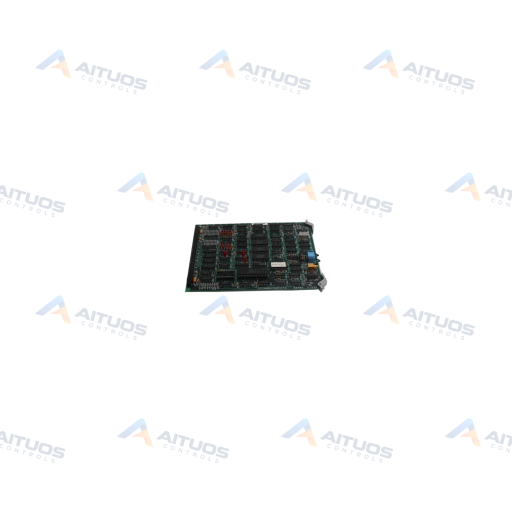
The General Electric DS200DCFBG2BNC is a Mark V power supply board. It operates within Speedtronic systems for gas and steam turbine management. This board represents a revised release of the original DS200DCFBG2 platform. It incorporates three distinct engineering revisions including functional and artwork updates. The board features normal assembly manufacturing and standard protective coating. The unit distributes operational power across turbine control architecture.
Hardware integration includes eighteen plug connectors and nine stab connectors. The nine stab terminals occupy the upper left corner of the board. Plug connectors range from two-pin configurations to larger multi-pin interfaces. Circuit protection includes three fuses paired with neon and diode status indicators. Seven onboard DIP switches select alternating-current line voltages and motor feedback circuits. Five test points and twelve jumpers support hardware diagnostic procedures.
TECHNICAL DATA
Technical Specifications
| Parameter | Specification |
|---|
| Abbreviation | DCFB |
|---|
| Assembly Type | Normal Assembly |
|---|
| Weight | 3.85 lb |
|---|
TECHNICAL INFORMATION
Features
- Includes eighteen plug connectors ranging from two pins to multi-pin designs.
- Provides nine stab connectors in the upper left corner labeled V1 through VM2BA.
- Integrates seven DIP switches to configure AC line voltage and motor feedback circuits.
- Features three protective fuses with dedicated neon and LED blown-fuse indicators.
- Contains twelve jumpers and five test points for diagnostic circuit testing.
- Incorporates seven transformers, an onboard relay, heat sinks, and over fifty resistor arrays.
TECHNICAL INFORMATION
Applications
- General Electric Mark V Speedtronic turbine control cabinets.
- Gas and steam turbine power generation and management systems.
TECHNICAL INFORMATION
Connections / Interfaces
- Eighteen plug connectors located across the board for signal and power routing.
- Nine stab connectors situated in the upper left corner for direct wiring.
- Stab connector points labeled V1, V2, V3, P1A, P2A, VM1A, VM1B, VB2A, and VM2BA.
TECHNICAL INFORMATION
Configuration Guidelines
- Adjust the seven DIP switches to select appropriate AC line input voltages.
- Configure voltage levels applied to the DC bridge and motor voltage feedback VCO circuits.
- Verify twelve jumper settings match the required Mark V turbine control setup.
PART VERIFICATION
Before You Order
Industrial automation parts can share similar model names, suffixes and revisions. Confirm the complete manufacturer Part Number before purchase.
01Check Part NumberMatch the complete ordering code on the existing unit.
02Confirm RevisionCheck suffix, hardware or firmware when applicable.
03Send a Label PhotoWe can review a clear label photo when identification is uncertain.
ORDERING PROCESS
From RFQ to Dispatch
1Submit Part Number2Verify Product Identity3Confirm Stock & Condition4Issue Quotation5Dispatch & Tracking
PRODUCT FAQ
Frequently Asked Questions
What system uses the General Electric DS200DCFBG2BNC board?
The board operates inside General Electric Mark V Speedtronic systems for gas and steam turbine control.
What is the function of the onboard DIP switches on the DS200DCFBG2BNC?
The seven DIP switches select AC line voltage and voltage applied to DC bridge motor feedback circuits.
How does the DS200DCFBG2BNC indicate blown fuses?
Blown fuses trigger onboard visual indicators, consisting of two light-emitting diodes and one neon indicator.
What connectors are present on the DS200DCFBG2BNC power supply board?
The unit includes eighteen multi-pin plug connectors and nine dedicated stab connectors.