PRODUCT INFORMATION
Product Overview
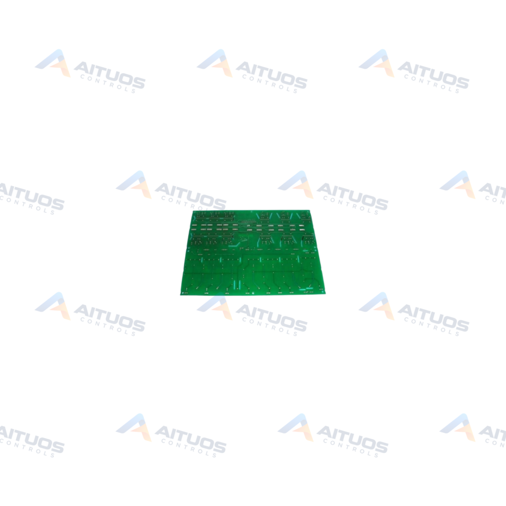
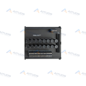
The General Electric DS200PCCAG5ACB is a Power Connect Card designed for the Mark V drive control system. It functions as an interface between an SCR power bridge and drive control circuitry. Pulse transformers on the board feed gate drive signals directly to the SCR bridge. This board is classified as a high horsepower PCCA configuration. Snubbers and attenuation strings are removed from the card and positioned elsewhere in the drive system.
The card incorporates 12 plug connectors to transmit forward and reverse gate pulse signals. Another plug connector enables dedicated communication with a DCFB power supply board. The circuit board mounts onto a carrier using six plastic holders behind drive control and power supply boards. Factory-drilled holes ringed with insulating material support secure mechanical mounting. The G5 group designation indicates a 1500 V rms maximum AX voltage rating.
TECHNICAL DATA
Technical Specifications
| Parameter | Specification |
|---|
| Instruction Manual | GEI-100161 |
|---|
| PCB Coating Type | Normal Coating |
|---|
| 1st Functional Revision | A |
|---|
| 2nd Functional Revision | C |
|---|
TECHNICAL INFORMATION
Features
- Transmits gate pulse signals to the SCR bridge via onboard pulse transformers.
- Provides 12 plug connectors for forward and reverse gate pulse distribution.
- Communicates with a DCFB-type power supply board using a dedicated plug connector.
- Configured with 4 wire jumpers labeled WP4, WP3, JP2, and JP1.
- Supports integration with leg reactors, fuses, and separate or common bus transformers.
TECHNICAL INFORMATION
Applications
- High horsepower motor controllers within Mark V automated drive assemblies.
- J, K, and M-style Mark V series frame installations.
TECHNICAL INFORMATION
Connections / Interfaces
- Twelve plug connectors interface forward and reverse pulse signals to the SCR bridge.
- One dedicated plug connector links directly to the DCFB power supply board.
TECHNICAL INFORMATION
Installation Guidelines
- Treat the board as static-sensitive during all handling, testing, and replacement steps.
- Discharge residual surface voltages that may persist after drive power is removed.
- Mount the unit behind drive control and power supply boards using six plastic holders.
- Fasten hardware through factory-drilled holes ringed with insulating material.
TECHNICAL INFORMATION
Configuration Guidelines
- Verify onboard jumper positions for WP4, WP3, JP2, and JP1 before energizing.
- Consult instruction manual GEI-100161 for exact system wiring and hardware setup.
TECHNICAL INFORMATION
Compatibility
- Compatible with J, K, and M-style Mark V automated drive frame components.
- Designed to operate with GE DCFB-type power supply boards.
COMPATIBILITY
Compatibility & Replacement
COMPATIBLE MODELSCompatible with J, K, and M-style Mark V automated drive frame components. Designed to operate with GE DCFB-type power supply boards.
Verify compatibility against the exact Part Number, revision and manufacturer documentation before ordering.
PART VERIFICATION
Before You Order
Industrial automation parts can share similar model names, suffixes and revisions. Confirm the complete manufacturer Part Number before purchase.
01Check Part NumberMatch the complete ordering code on the existing unit.
02Confirm RevisionCheck suffix, hardware or firmware when applicable.
03Send a Label PhotoWe can review a clear label photo when identification is uncertain.
ORDERING PROCESS
From RFQ to Dispatch
1Submit Part Number2Verify Product Identity3Confirm Stock & Condition4Issue Quotation5Dispatch & Tracking
PRODUCT FAQ
Frequently Asked Questions
What is the primary role of the GE DS200PCCAG5ACB?
The board interfaces the SCR power bridge with drive control circuitry using pulse transformers.
Which drive frames support the DS200PCCAG5ACB card?
The card is compatible with J, K, and M-style Mark V automated drive frame components.
Which power supply board connects to the DS200PCCAG5ACB?
The card connects directly to a Mark V DCFB-type power supply board.