PRODUCT INFORMATION
Product Overview
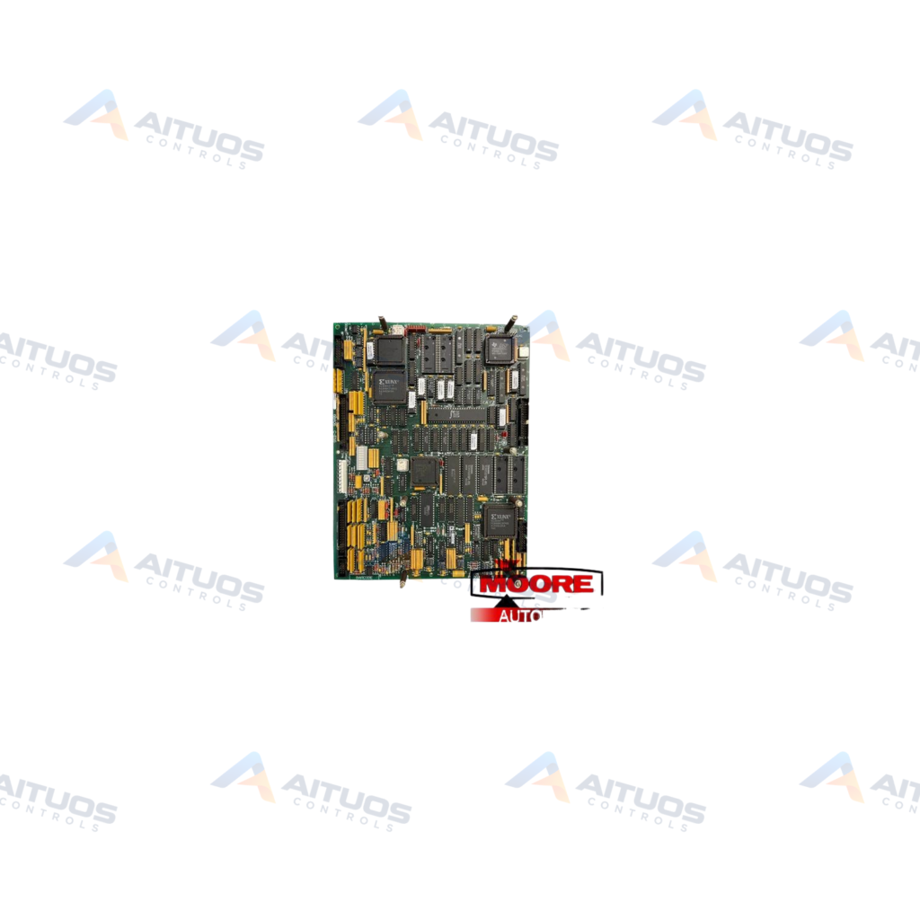
The General Electric DS200SDCCG4AGD is a Mark V Drive Control Card for turbine automated drive systems. It serves as the primary controller for compatible gas, steam, and wind turbine assemblies. This board integrates Speedtronic control technology to manage turbine drive operation. Three onboard microprocessors handle assigned control tasks across the card. Shared onboard RAM permits simultaneous data access by multiple microprocessors.
Ten inline diagnostic LEDs provide status monitoring and fault identification. The indicators flash sequentially from left to right during normal drive operation. When a fault occurs, the LEDs display numeric diagnostic codes directly. Two dedicated interface connectors link this card to the external Power Supply Interface Board. One connector transmits input and output signals, while the second delivers internal DC voltage. The assembly incorporates normal PCB protective coating and voltage suppression components.
TECHNICAL DATA
Technical Specifications
| Parameter | Specification |
|---|
| Instruction Manual | GEI-100029 |
|---|
| PCB Coating | Normal Coating |
|---|
TECHNICAL INFORMATION
Features
- Operates as the primary drive controller within General Electric Mark V turbine assemblies.
- Includes three dedicated microprocessors to distribute drive control processing functions.
- Features shared RAM for concurrent multi-processor data access.
- Provides ten diagnostic LEDs configured for status and numerical error code readouts.
- Connects to the Power Supply Interface Board via two separate dedicated connectors.
- Incorporates protective normal PCB coating and hardware voltage suppression components.
TECHNICAL INFORMATION
Applications
- General Electric Mark V gas turbine drive control systems.
- Steam turbine automated drive assemblies.
- Industrial wind turbine drive control systems.
TECHNICAL INFORMATION
Connections / Interfaces
- Two connectors interface directly with the Power Supply Interface Board.
- One connector carries drive input and output signals.
- The second connector delivers direct current operating voltage from the power supply.
- Onboard connectors provide communication links to optional cards and drive control boards.
TECHNICAL INFORMATION
Installation Guidelines
- Drive cabinets contain hazardous electrical currents that can cause severe shock or burns.
- De-energize the drive system completely before touching components inside the drive cabinet.
- Mount the board facing the front cabinet door to keep diagnostic LEDs visible.
TECHNICAL INFORMATION
Configuration Guidelines
- Configure diagnostic LEDs to monitor drive runtime variables during operation.
- Refer to GE instruction manual GEI-100029 for configuration instructions and error codes.
PART VERIFICATION
Before You Order
Industrial automation parts can share similar model names, suffixes and revisions. Confirm the complete manufacturer Part Number before purchase.
01Check Part NumberMatch the complete ordering code on the existing unit.
02Confirm RevisionCheck suffix, hardware or firmware when applicable.
03Send a Label PhotoWe can review a clear label photo when identification is uncertain.
ORDERING PROCESS
From RFQ to Dispatch
1Submit Part Number2Verify Product Identity3Confirm Stock & Condition4Issue Quotation5Dispatch & Tracking
PRODUCT FAQ
Frequently Asked Questions
What is the primary function of the DS200SDCCG4AGD?
It serves as the primary controller for compatible General Electric Mark V turbine drive systems.
How do the diagnostic LEDs indicate drive errors?
Ten LEDs display numeric fault codes when errors occur. The first two LEDs display hundreds. The next four show tens, and the final four indicate units.
How does the DS200SDCCG4AGD connect to the power supply?
Two dedicated connectors link the board to the Power Supply Interface Board. One transmits I/O signals, while the other provides operating DC voltage.