PRODUCT INFORMATION
Product Overview
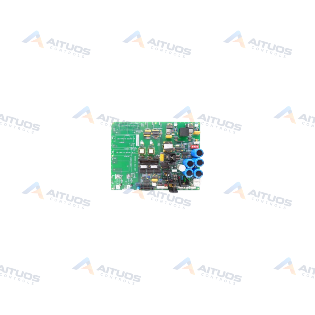
The General Electric DS200SDCIG2ABA is a Mark V power supply board. It functions inside DC2000 drive systems with AC input ratings up to 600 V AC. The board incorporates motor field power circuits configured without an onboard SCR module. It also includes driver circuits dedicated to armature SCR gating functions. Instrumental circuits monitor armature current, armature voltage, field current, AC line parameters, and phase sequence signals.
Circuit protection includes fuses FU1 through FU6 paired with individual LED diagnostic indicators. Hardware configuration utilizes Berg-type manually movable jumpers JP1, JP2, and SW1 for operational settings. The assembly mounts behind the companion SDCC board on the drive base plate. Detachable plastic snaps secure the circuit board in position. This model features normal PCB coating for industrial enclosure service.
TECHNICAL DATA
Technical Specifications
| Parameter | Specification |
|---|
| PCB Coating | Normal Coating |
|---|
| Use Cases | For DC2000 drives with input voltages up to 600 V AC |
|---|
| Special Notes | Used with External Exciters |
|---|
| Instruction Manual | GEI-100173 |
|---|
| Weight | 1 lb |
|---|
TECHNICAL INFORMATION
Features
- Operates in DC2000 drive systems with line input voltages up to 600 V AC.
- Contains motor field power circuits designed for external exciter setups.
- Provides dedicated driver circuits for armature SCR gating.
- Integrates instrumentation monitoring for AC and DC line motor signals.
- Features protective fuses FU1 through FU6 with individual diagnostic LEDs.
- Includes Berg-type manually movable jumpers JP1, JP2, and SW1.
- Supplied with normal protective PCB coating.
TECHNICAL INFORMATION
Applications
- General Electric DC2000 drive cabinets with input voltages up to 600 V AC.
- Industrial drive installations configured with external exciters.
TECHNICAL INFORMATION
Connections / Interfaces
- Ribbon cable and pull-tab connections interface directly with adjacent drive modules.
- Dedicated circuit paths route gate signals and instrumental feedback lines.
TECHNICAL INFORMATION
Installation Guidelines
- Disconnect all electrical power before servicing or replacing the board.
- Lethal voltages can remain present across components even after rest.
- Disengage cabinet door locks to access internal drive sections.
- Lift and tilt the front SDCC module forward to expose the assembly.
- Disconnect ribbon cables and pull-tab connectors with care.
- Release detachable plastic snaps to free the board from the base plate.
- Verify that all connector cables are fully seated during reassembly.
TECHNICAL INFORMATION
Configuration Guidelines
- Configure Berg-type jumpers JP1, JP2, and SW1 to select required system settings.
- Match all jumper configurations to the previous board before applying electrical power.
- Consult instruction manual GEI-100173 for specific jumper test and customer options.
TECHNICAL INFORMATION
Compatibility
- Compatible with General Electric DC2000 drive platforms using external exciters.
- Mounts directly behind the companion SDCC module on the cabinet base plate.
COMPATIBILITY
Compatibility & Replacement
COMPATIBLE MODELSCompatible with General Electric DC2000 drive platforms using external exciters. Mounts directly behind the companion SDCC module on the cabinet base plate.
Verify compatibility against the exact Part Number, revision and manufacturer documentation before ordering.
PART VERIFICATION
Before You Order
Industrial automation parts can share similar model names, suffixes and revisions. Confirm the complete manufacturer Part Number before purchase.
01Check Part NumberMatch the complete ordering code on the existing unit.
02Confirm RevisionCheck suffix, hardware or firmware when applicable.
03Send a Label PhotoWe can review a clear label photo when identification is uncertain.
ORDERING PROCESS
From RFQ to Dispatch
1Submit Part Number2Verify Product Identity3Confirm Stock & Condition4Issue Quotation5Dispatch & Tracking
PRODUCT FAQ
Frequently Asked Questions
What drive systems use the General Electric DS200SDCIG2ABA?
The board operates in GE DC2000 drive systems with input line voltages up to 600 V AC.
Where does the DS200SDCIG2ABA mount inside the drive assembly?
The board sits behind the companion SDCC module on the base plate. Tilt the SDCC module forward to access the board.
What onboard configuration hardware is present on the DS200SDCIG2ABA?
The board includes Berg-type manually movable jumpers designated as JP1, JP2, and SW1.
What onboard circuit protection does this power supply board provide?
The assembly features protective fuses FU1 through FU6 accompanied by diagnostic LED indicators.