PRODUCT INFORMATION
Product Overview
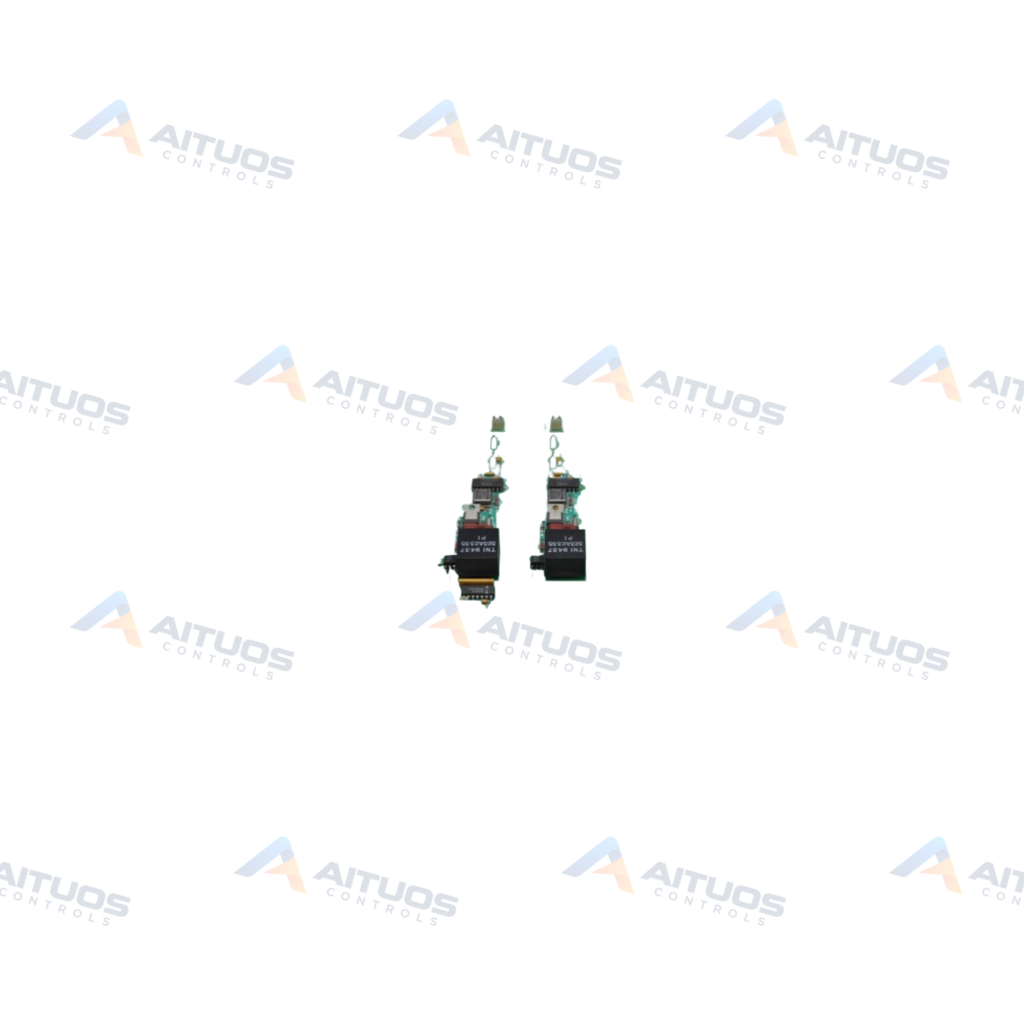
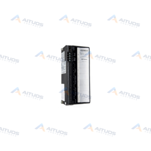
The General Electric DS200SHVMG1ACC is an SCR High Voltage M-Frame Interface Board for Mark V control systems. It interfaces the SCR bridge on M-frame drives with DCFB or SDCI power supply boards. The board also connects directly with the PCCA powerconnect card in the drive assembly. This unit functions within control systems for compatible wind, steam, and gas turbine drive assemblies.
The board converts shunt signals from -500 to 500 mV into differential frequency outputs. These output frequencies range from 0 to 500 kHz. Conversions use onboard DC positive and negative voltage controlled oscillator circuits. It supplies AC line currents with a 10:1 current transformer attenuation factor. Engineers configure attenuation requirements using seventeen onboard jumpers.
TECHNICAL DATA
Technical Specifications
| Parameter | Specification |
|---|
| Instruction Manual | GEI-100174 |
|---|
| PCB Coating | Normal Coating |
|---|
| 1st Functional Revision | A |
|---|
| 2nd Functional Revision | C |
|---|
TECHNICAL INFORMATION
Features
- Converts -500 to 500 mV shunt inputs into 0 to 500 kHz differential frequency outputs.
- Features positive and negative voltage controlled oscillator circuits for signal conversion.
- Provides 10:1 current transformer attenuation for AC line current monitoring.
- Includes seventeen onboard configuration jumpers to select attenuation parameters.
- Supports direct interfacing with PCCA powerconnect cards and DCFB or SDCI boards.
- Equipped with factory-labeled I/O connectors including IA2PL-1 and IA2PL-2 differential outputs.
TECHNICAL INFORMATION
Applications
- Gas turbine automated drive control systems.
- Steam turbine drive assemblies within GE Mark V platforms.
- Wind turbine control assemblies utilizing M-frame drive hardware.
TECHNICAL INFORMATION
Connections / Interfaces
- IA2PL-1 connector provides the motor armature current shunt differential VCO positive output.
- IA2PL-2 connector provides the motor armature current shunt differential VCO negative output.
- Multiple stab style connectors distribute high-voltage interface signals across the assembly.
- Direct interface paths route to DCFB, SDCI, and PCCA hardware boards.
TECHNICAL INFORMATION
Installation Guidelines
- Follow all provided drive installation parameters to avoid damage to internal components.
- Verify voltage-limiting rectifiers, capacitors, and resistors are intact prior to installation.
TECHNICAL INFORMATION
Configuration Guidelines
- Configure the seventeen onboard jumpers to select the required line current attenuation.
- Refer to instruction manual GEI-100174 for exact jumper placement maps.
PART VERIFICATION
Before You Order
Industrial automation parts can share similar model names, suffixes and revisions. Confirm the complete manufacturer Part Number before purchase.
01Check Part NumberMatch the complete ordering code on the existing unit.
02Confirm RevisionCheck suffix, hardware or firmware when applicable.
03Send a Label PhotoWe can review a clear label photo when identification is uncertain.
ORDERING PROCESS
From RFQ to Dispatch
1Submit Part Number2Verify Product Identity3Confirm Stock & Condition4Issue Quotation5Dispatch & Tracking
PRODUCT FAQ
Frequently Asked Questions
What is the primary function of the DS200SHVMG1ACC interface board?
The board interfaces M-frame SCR bridges with DCFB, SDCI, and PCCA cards. It converts shunt signals into differential frequencies.
How does the DS200SHVMG1ACC convert shunt signals?
It uses DC positive and negative voltage controlled oscillator circuits. Signals from -500 to 500 mV become 0 to 500 kHz outputs.
How is line current attenuation configured on this board?
Line current attenuation uses seventeen onboard jumpers to adjust current transformer ratios. Instruction manual GEI-100174 outlines settings.
What pricing is available for the DS200SHVMG1ACC?
Current pricing is provided upon inquiry. Quotes reflect condition and stock. Indicative market reference only; not a final quotation.