PRODUCT INFORMATION
Product Overview
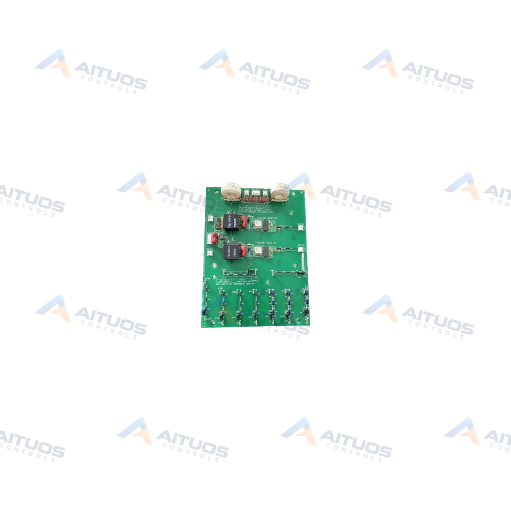
The General Electric DS200SHVMG1AFE is an SCR high voltage M-frame interface board for Mark V turbine systems. This board establishes communication between the M-frame drive SCR bridge, power supply boards, and the power connect card. It operates across General Electric drives and turbine exciters. Supported systems include gas, steam, and wind turbine drive assemblies.
This interface board performs signal conversion and electrical monitoring functions inside the drive assembly. A voltage controlled oscillator circuit converts shunt signals from -500 to 500 mV. It produces differential frequency outputs rated from 0 to 500 kHz. The board transmits these digitized signals to the DCFB or SDCI power supply and PCCA card.
TECHNICAL DATA
Technical Specifications
| Parameter | Specification |
|---|
| Instruction Manual | GEI-100174 |
|---|
| PCB Coating | Normal Coating |
|---|
| Mark V Series Grouping | Group 1 |
|---|
TECHNICAL INFORMATION
Features
- Converts -500 to 500 mV shunt inputs to 0 to 500 kHz differential frequency outputs.
- Integrates a voltage controlled oscillator circuit using DC positive and negative shunts.
- Provides selectable 10:1 current transformer attenuation for phase A and phase C lines.
- Contains 17 onboard hardware jumpers for circuit attenuation and signal configuration.
- Protected by normal printed circuit board coating applied across functional components.
TECHNICAL INFORMATION
Applications
- Mark V Speedtronic turbine control and management systems.
- Gas and steam turbine automated drive assemblies.
- Wind turbine power generation control setups.
- General Electric industrial M-frame drive lineups and exciter cabinets.
TECHNICAL INFORMATION
Connections / Interfaces
- SCR bridge interface for M-frame motor drives.
- Direct signal link to DCFB or SDCI power supply boards.
- Terminal communication connection to the PCCA power connect card.
- Wiring plug and stab connector connection points.
TECHNICAL INFORMATION
Installation Guidelines
- De-energize all drive power inputs prior to servicing or replacement.
- Wait several minutes after power removal for voltage-limiting capacitors to discharge safely.
- Handle the board in an electrostatic-safe workspace to protect voltage-sensitive components.
- Verify jumper orientation prior to re-energizing the M-frame drive system.
TECHNICAL INFORMATION
Configuration Guidelines
- Set jumpers JP1 through JP8 to identical matching positions.
- Use jumpers JP1 through JP8 to select or bypass 10:1 current transformer attenuation.
- Configure additional jumpers to establish desired line attenuation strings.
- Consult instruction manual GEI-100174 for complete jumper mapping tables.
TECHNICAL INFORMATION
Compatibility
- Operates within General Electric Mark V control system architectures.
- Interfaces with DCFB and SDCI power supply boards.
- Connects directly with General Electric PCCA power connect cards.
TECHNICAL INFORMATION
Lifecycle / Replacement Information
- Contains three factory revisions updating the base DS200SHVMG1 design.
- Classified under Group 1 product groupings within the Mark V system platform.
COMPATIBILITY
Compatibility & Replacement
COMPATIBLE MODELSOperates within General Electric Mark V control system architectures. Interfaces with DCFB and SDCI power supply boards. Connects directly with General Electric PCCA power connect cards.
Verify compatibility against the exact Part Number, revision and manufacturer documentation before ordering.
PART VERIFICATION
Before You Order
Industrial automation parts can share similar model names, suffixes and revisions. Confirm the complete manufacturer Part Number before purchase.
01Check Part NumberMatch the complete ordering code on the existing unit.
02Confirm RevisionCheck suffix, hardware or firmware when applicable.
03Send a Label PhotoWe can review a clear label photo when identification is uncertain.
ORDERING PROCESS
From RFQ to Dispatch
1Submit Part Number2Verify Product Identity3Confirm Stock & Condition4Issue Quotation5Dispatch & Tracking
PRODUCT FAQ
Frequently Asked Questions
What is the primary function of the DS200SHVMG1AFE board?
It provides signal conversion and interface links between the SCR bridge, power supplies, and connect cards.
How must jumpers JP1 through JP8 be configured?
Jumpers JP1 through JP8 must all share the same position to select or bypass 10:1 CT attenuation.
Which power supply boards interface with the DS200SHVMG1AFE?
The board communicates directly with either DCFB or SDCI power supply circuit boards.
Why is a delay required before touching the board after power shutoff?
Onboard capacitors retain electrical charge. Maintenance requires waiting several minutes for internal voltages to dissipate.