PRODUCT INFORMATION
Product Overview
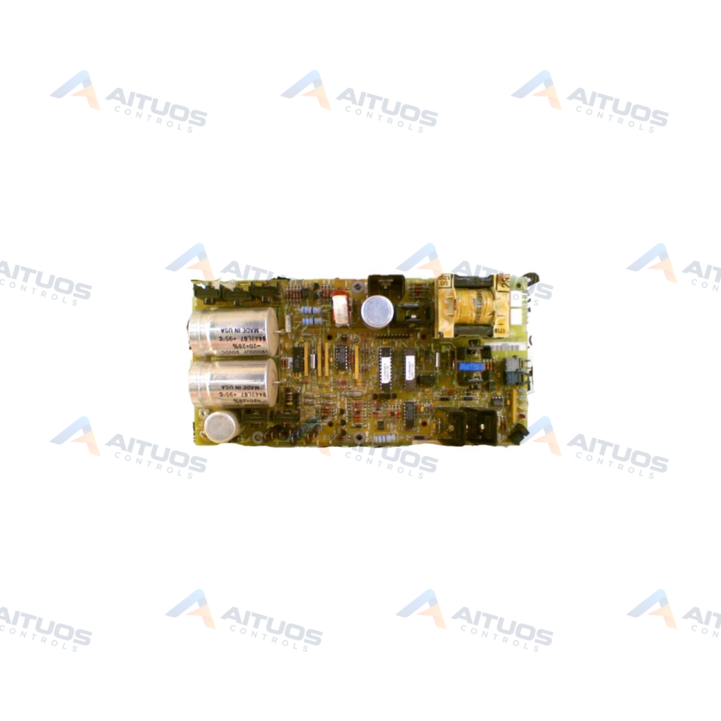
The General Electric DS200TCQAG1B is an RST Analog I/O Board for Mark V gas turbine control systems. This board conditions and scales analog signals received from terminal boards mounted in cores R1, R2, and R3. It handles LVDT position inputs, servo valve outputs, thermocouple inputs, and 4-20 mA current loops. The unit also processes vibration signals, pulse rate inputs, relay driver outputs, and generator line signals.
Signal transmission to the core data bus occurs over the dedicated 3PL connector toward the STCA board. The JE connector routes pulse signals, line measurements, and servo driver commands directly to the TCQC board. Thermocouple readings arrive from the TBQA terminal board via connector JA for integrated cold junction calculation. Direct 4-20 mA transducer loops connect across terminal board TBQC through connector JB.
TECHNICAL DATA
Technical Specifications
| Parameter | Specification |
|---|
| HARDWARE | The mA output circuits are selected using the hardware jumpers J1 and J2. The mA output current range, either 20 mA maximum or 200 mA maximum, is configured using J5 and J6. For card tests, the RS232 port is used in J7. J8 turns on an oscillator. For details on the hardware jumper settings for this board, consult Appendix A and the operator interface's hardware jumper panel. |
|---|
| SOFTWARE | Thermocouple, pulse rate, vibration, LVDT position, and 420 mA input and output I/O Configuration constants are entered in the I/O Configuration Editor found on the operator interface as explained below. |
|---|
TECHNICAL INFORMATION
Features
- Conditions analog signals across Mark V I/O cores R1, R2, and R3.
- Accepts thermocouple, LVDT, vibration, pulse rate, and 4-20 mA inputs.
- Provides analog output circuitry for 4-20 mA devices and servo valve drivers.
- Communicates across core data bus lines through the 3PL connector interface.
- Configurable mA output range supporting 20 mA or 200 mA selections.
TECHNICAL INFORMATION
Applications
- Speedtronic Mark V gas turbine control and protection architectures.
- Analog transducer scaling and conditioning in turbine control cores.
- Speed pulse detection and servo valve position regulation.
TECHNICAL INFORMATION
Connections / Interfaces
- Connector 2PL distributes operating power sourced from the TCPS power distribution board.
- Connector 3PL links data bus lines among STCA, TCQA, and TCQE boards.
- Connector JA carries thermocouple inputs and cold junction references from board TBQA.
- Connector JB interfaces 4-20 mA inputs and outputs with terminal board TBQC.
- Connector JE exchanges pulse, generator, line, relay driver, and servo driver signals.
- Connector JF receives LVDT and LVDR position inputs from terminal board TBQC.
- Connector JG routes vibration and +/- 10 V dc inputs from board TBQB.
TECHNICAL INFORMATION
Installation Guidelines
- Mount the board in the designated card slot within the Mark V core.
- Connect terminal ribbon cables firmly to connectors JA, JB, JE, JF, and JG.
- Confirm power bus connection 2PL is seated before energizing the cabinet.
TECHNICAL INFORMATION
Configuration Guidelines
- Hardware jumpers J1 and J2 select the active milliampere output circuits.
- Jumpers J5 and J6 set maximum output current ranges to 20 mA or 200 mA.
- Jumper J7 provides RS232 port connection access for dedicated card tests.
- Jumper J8 activates an onboard oscillator circuit during system operation.
- Software I/O configuration constants are defined within the operator interface configuration editor.
TECHNICAL INFORMATION
Compatibility
- General Electric Speedtronic Mark V control systems.
- Terminal boards TBQA, TBQB, TBQC, QTBA, and PTBA.
- Core interface boards STCA, TCQC, and TCQE.
COMPATIBILITY
Compatibility & Replacement
COMPATIBLE MODELSGeneral Electric Speedtronic Mark V control systems. Terminal boards TBQA, TBQB, TBQC, QTBA, and PTBA. Core interface boards STCA, TCQC, and TCQE.
Verify compatibility against the exact Part Number, revision and manufacturer documentation before ordering.
PART VERIFICATION
Before You Order
Industrial automation parts can share similar model names, suffixes and revisions. Confirm the complete manufacturer Part Number before purchase.
01Check Part NumberMatch the complete ordering code on the existing unit.
02Confirm RevisionCheck suffix, hardware or firmware when applicable.
03Send a Label PhotoWe can review a clear label photo when identification is uncertain.
ORDERING PROCESS
From RFQ to Dispatch
1Submit Part Number2Verify Product Identity3Confirm Stock & Condition4Issue Quotation5Dispatch & Tracking
PRODUCT FAQ
Frequently Asked Questions
What primary function does the DS200TCQAG1B board perform in Mark V systems?
The DS200TCQAG1B scales and conditions analog inputs and outputs across R1, R2, and R3 cores.
How are the analog output current ranges configured on the DS200TCQAG1B?
Hardware jumpers J5 and J6 set the mA output current range to 20 mA or 200 mA maximum.
Which connectors interface the DS200TCQAG1B with external terminal boards?
Connectors JA, JB, JF, and JG connect to terminal boards TBQA, TBQC, and TBQB directly.