PRODUCT INFORMATION
Product Overview
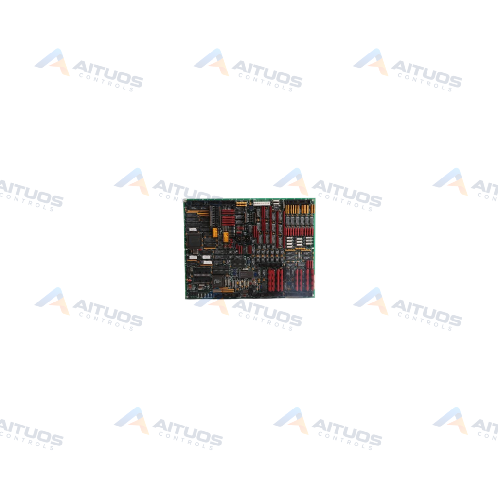
The General Electric DS215TCQAG1BZZ01A is a Mark V Circuit Board and Firmware unit. It operates within Speedtronic Mark V control systems for automated turbine drives. Supported prime movers include steam, gas, and wind turbine assemblies. This board incorporates dedicated firmware indicated by the ZZ01A catalog suffix. It provides targeted control functions in the turbine cabinet architecture.
The assembly includes six 34-pin connectors and two 40-pin connectors for internal cabinet wiring. Six onboard diagnostic LEDs arrange into two rows of three indicators. Operators can view these active indicators directly through the front cabinet glass. Flashing LED sequences communicate real-time activity and circuit fault statuses. Proper identification labels assist technicians during ribbon cable disconnection and field replacement.
TECHNICAL DATA
Technical Specifications
| Parameter | Specification |
|---|
| Instruction Manual | GEH-6195 |
|---|
| PCB Coating | Normal Coating |
|---|
TECHNICAL INFORMATION
Features
- Configured with factory firmware identified by the ZZ01A product suffix.
- Includes six 34-pin ribbon connectors labeled JA, JB, JD, JE, JG, and 3PL.
- Features two 40-pin connectors alongside six onboard configuration jumpers.
- Equipped with six diagnostic status LEDs visible through the enclosure window.
- Applies standard normal protective coating across the printed circuit board assembly.
TECHNICAL INFORMATION
Applications
- General Electric Speedtronic Mark V steam turbine control assemblies.
- Gas turbine drive management and automation systems.
- Wind turbine automation and control drive cabinets.
TECHNICAL INFORMATION
Connections / Interfaces
- Six 34-pin ribbon cable connectors designated JA, JB, JD, JE, JG, and 3PL.
- Two 40-pin internal interface cable connectors.
- Six onboard jumpers for hardware configuration.
TECHNICAL INFORMATION
Installation Guidelines
- Inspect the existing circuit board inside the drive enclosure before removal.
- Label every ribbon cable with its corresponding printed connector ID.
- Grasp ribbon cables by the connector housing when disconnecting from pins.
- Verify jumper configurations match the replaced unit prior to powering up.
TECHNICAL INFORMATION
Compatibility
- Compatible with General Electric Mark V Speedtronic turbine control cabinets.
- Derived from the DS215TCQAG1 base printed circuit board platform.
TECHNICAL INFORMATION
Lifecycle / Replacement Information
- The DS215TCQAG1BZZ01A represents a firmware-equipped version of the DS215TCQAG1 parent board.
- Speedtronic Mark V system hardware is maintained for legacy turbine support.
COMPATIBILITY
Compatibility & Replacement
COMPATIBLE MODELSCompatible with General Electric Mark V Speedtronic turbine control cabinets. Derived from the DS215TCQAG1 base printed circuit board platform.
Verify compatibility against the exact Part Number, revision and manufacturer documentation before ordering.
PART VERIFICATION
Before You Order
Industrial automation parts can share similar model names, suffixes and revisions. Confirm the complete manufacturer Part Number before purchase.
01Check Part NumberMatch the complete ordering code on the existing unit.
02Confirm RevisionCheck suffix, hardware or firmware when applicable.
03Send a Label PhotoWe can review a clear label photo when identification is uncertain.
ORDERING PROCESS
From RFQ to Dispatch
1Submit Part Number2Verify Product Identity3Confirm Stock & Condition4Issue Quotation5Dispatch & Tracking
PRODUCT FAQ
Frequently Asked Questions
What is the primary function of the DS215TCQAG1BZZ01A board?
It functions as a circuit board with firmware for GE Mark V turbine drive systems. It handles analog input and output operations.
What do the six onboard LEDs indicate during turbine operation?
The LEDs indicate operating health across six board functions. They flash during processing and signal detected functional faults.
Which instruction manual covers the DS215TCQAG1BZZ01A?
General Electric instruction manual GEH-6195 details installation and diagnostic procedures for this hardware assembly.