PRODUCT INFORMATION
Product Overview
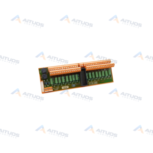
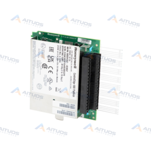
The Honeywell 900RSM-0101 is a ControlEdge redundancy switch module. It mounts in a redundant CPU rack between controller CPU-A and controller CPU-B. The unit coordinates execution between primary lead and secondary reserve processors. It supports Honeywell C75 and C75S controller architectures.
This hardware module provides physical status display and local manual control via a keyed switch. Automatic failover triggers on processor exceptions or loss of communication with remote I/O racks. Failover executes within four analog-control cycles or less during switchover events. Connected analog and digital output states remain maintained at the I/O racks during failover.
TECHNICAL DATA
Technical Specifications
| Parameter | Specification |
|---|
| Module type | Redundancy Switch Module; not a remote scanner |
|---|
| Compatible controllers | C75 and C75S only |
|---|
| Rack position | Installed between CPU-A on the left and CPU-B on the right |
|---|
| Redundant rack population | Two power supplies, two C75/C75S CPUs, and one RSM |
|---|
| Indicators | Lead and Reserve controller-status indicators |
|---|
| Local control | Keyed switch provides mode change and manual failover |
|---|
| Manual failover | Hold Failover until both Reserve lights illuminate, then release |
|---|
| Failover time | Four analog-control cycles or less |
|---|
| Automatic failover triggers | Includes loss of I/O-rack communications and processor exception |
|---|
| Output behavior during failover | Analog and digital output states are maintained at the I/O racks |
|---|
| Module power | 0.1 W HC900 hardware power; 0 W field power |
|---|
| Label electrical rating | 22 mA maximum at 5 VDC |
|---|
| Temperature code | T6 |
|---|
TECHNICAL INFORMATION
Features
- Designed specifically for redundant configurations using C75 and C75S controllers.
- Front keyed switch provides mode change control and manual failover capability.
- Dual status indicators display Lead and Reserve operating states for both controllers.
- Failover transfer completes within four analog-control execution cycles or less.
- Operates with low electrical power draw rated at 22 mA maximum at 5 VDC.
- Rated with a T6 temperature code for industrial environments.
TECHNICAL INFORMATION
Applications
- High-availability process automation using redundant CPU racks.
- Safety instrumented systems requiring uninterrupted supervisory control in SIL-compatible architectures.
- Industrial automation loops requiring maintained field output states during processor failovers.
TECHNICAL INFORMATION
Connections / Interfaces
- Installs directly into the dedicated center rack position between CPU-A and CPU-B.
- Interfaces directly across the redundant backplane to coordinate dual controller modules.
TECHNICAL INFORMATION
Installation Guidelines
- Install the module in the designated rack slot between CPU-A on the left and CPU-B on the right.
- A standard redundant rack population requires two power supplies, two C75 or C75S CPUs, and one switch module.
TECHNICAL INFORMATION
Configuration Guidelines
- Confirm that redundant CPU component model numbers have matching ZZ suffix digits before installation.
- To trigger manual failover, hold the keyed switch in Failover position until both Reserve lights illuminate, then release.
TECHNICAL INFORMATION
Compatibility
- Compatible exclusively with Honeywell C75 and C75S controllers.
- Designed for redundant rack layouts alongside dual redundant power supply modules.
- Not compatible for use as a remote I/O scanner.
TECHNICAL INFORMATION
Lifecycle / Replacement Information
- Listed as a SIL compatible module in Honeywell HC900 system documentation.
TECHNICAL INFORMATION
Compliance and Certifications
- SIL compatible module verified in Honeywell HC900 system documentation.
- Temperature code T6 rated.
TECHNICAL RESOURCES
Documentation
COMPATIBILITY
Compatibility & Replacement
COMPATIBLE MODELSCompatible exclusively with Honeywell C75 and C75S controllers. Designed for redundant rack layouts alongside dual redundant power supply modules. Not compatible for use as a remote I/O scanner.
Verify compatibility against the exact Part Number, revision and manufacturer documentation before ordering.
PART VERIFICATION
Before You Order
Industrial automation parts can share similar model names, suffixes and revisions. Confirm the complete manufacturer Part Number before purchase.
01Check Part NumberMatch the complete ordering code on the existing unit.
02Confirm RevisionCheck suffix, hardware or firmware when applicable.
03Send a Label PhotoWe can review a clear label photo when identification is uncertain.
ORDERING PROCESS
From RFQ to Dispatch
1Submit Part Number2Verify Product Identity3Confirm Stock & Condition4Issue Quotation5Dispatch & Tracking
PRODUCT FAQ
Frequently Asked Questions
Which controllers work with the Honeywell 900RSM-0101?
The 900RSM-0101 redundancy switch module is compatible exclusively with C75 and C75S controllers.
What happens to field outputs during an automatic failover?
Analog and digital output states are maintained at the I/O racks during failover.
Where does the 900RSM-0101 install within the redundant rack?
It installs in the designated position between CPU-A on the left and CPU-B on the right.
How quickly does the 900RSM-0101 execute a failover?
Failover completes within four analog-control cycles or less upon an exception trigger.
What are the compatibility requirements for redundant components in the rack?
For redundant CPU systems, component model numbers must share matching ZZ suffix numbers.