PRODUCT INFORMATION
Product Overview
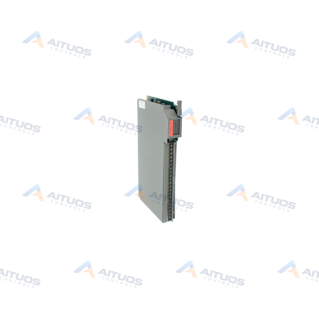
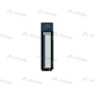
The Allen-Bradley 1771-IAD is a Digital AC/DC Input Module for the PLC-5 series platform. It provides sixteen discrete input channels designed for 120V AC and 125V DC operational categories. Operating voltage ranges from 79 to 138 Volts AC or DC across industrial field devices. The hardware interfaces discrete pushbuttons, limit switches, selector switches, and auxiliary relay contacts directly to control logic.
The module mounts into 1771 universal I/O chassis including 1771-A1B through 1771-A4B, 1771-AM1, and 1771-AM2. Field terminations wire directly to a detachable 1771-WH field wiring arm. This configuration allows module replacement without disconnecting individual field signal conductors. Backplane current draw equals 195 milliamperes at 5 Volts DC. Maximum power dissipation reaches 8.8 Watts with optoelectrical circuit isolation and hardware input filtering.
TECHNICAL DATA
Technical Specifications
| Parameter | Specification |
|---|
| AC Operating Voltage | 79-138 Volts |
|---|
| Backplane Current | 195 Miliamperes |
|---|
| Category | PLCs |
|---|
| DC Operating Voltage | 79-138 Volts |
|---|
| GTIN | 10662468177624 |
|---|
| Max AC Off-State Current | 2.8 Miliamperes |
|---|
| Module Location | 1771-A1B, A2B, A3B, A3B1, A4B, 1771-AM1 and AM2 chassis. |
|---|
| Module Type | Digital AC/DC Input Module |
|---|
| Number of Inputs | 16 Inputs |
|---|
| Typical AC Signal Delay (Off) | 25 (+/- 5) ms |
|---|
| Typical AC Signal Delay (On) | 5 (+/- 3) ms |
|---|
| Typical DC Signal Delay (Off) | 25 (+/- 5) ms |
|---|
| Typical DC Signal Delay (On) | 3 (+/- 0.1) or 10 (+/- 1) ms |
|---|
| UPC | 10662468177624 |
|---|
| Voltage Category | 120 Volts AC/DC |
|---|
| Weight | 2.38 lbs (1.08 kg) |
|---|
| Wiring Arm | 1771-WH |
|---|
TECHNICAL INFORMATION
Features
- Provides 16 discrete input channels operating across 120V AC and DC nominal levels.
- Operates over an input voltage span of 79 to 138 Volts AC or DC.
- Features optoelectrical isolation to shield internal logic circuits from field electrical transients.
- Includes selectable signal delay filtering to reduce high-frequency electrical noise.
- Displays logic side channel status via 16 red indicators and one green active indicator.
- Supports 1/2-slot, 1-slot, and 2-slot I/O addressing within 1771 chassis assemblies.
- Utilizes the detachable 1771-WH field wiring arm for modular pre-wiring.
TECHNICAL INFORMATION
Applications
- Interfacing pushbuttons, selector switches, and limit switches to PLC-5 systems.
- Monitoring auxiliary contacts from motor starters, relays, and contactors.
- Acquiring discrete on/off signals from plant annunciators and field instrumentation.
TECHNICAL INFORMATION
Connections / Interfaces
- Connects to field wiring via the 1771-WH field wiring arm.
- Engages 1771 backplane connectors using upper keying pins 14-16 and lower keying pins 10-12.
TECHNICAL INFORMATION
Installation Guidelines
- Place keying bands on the backplane connector between pins 10 and 12 on the bottom.
- Place keying bands on the backplane connector between pins 14 and 16 on the top.
- Mount the 1771-WH wiring arm on the chassis before inserting the module.
TECHNICAL INFORMATION
Configuration Guidelines
- Select input delay response times to match field signal dynamics and noise suppression needs.
- Configure module addressing switches in the chassis for 1/2-slot, 1-slot, or 2-slot modes.
TECHNICAL INFORMATION
Compatibility
- Compatible with Allen-Bradley 1771-A1B, 1771-A2B, 1771-A3B, 1771-A3B1, and 1771-A4B chassis.
- Compatible with 1771-AM1 and 1771-AM2 chassis systems.
- Requires the 1771-WH field wiring arm for terminal terminations.
COMPATIBILITY
Compatibility & Replacement
COMPATIBLE MODELSCompatible with Allen-Bradley 1771-A1B, 1771-A2B, 1771-A3B, 1771-A3B1, and 1771-A4B chassis. Compatible with 1771-AM1 and 1771-AM2 chassis systems. Requires the 1771-WH field wiring arm for terminal terminations.
Verify compatibility against the exact Part Number, revision and manufacturer documentation before ordering.
PART VERIFICATION
Before You Order
Industrial automation parts can share similar model names, suffixes and revisions. Confirm the complete manufacturer Part Number before purchase.
01Check Part NumberMatch the complete ordering code on the existing unit.
02Confirm RevisionCheck suffix, hardware or firmware when applicable.
03Send a Label PhotoWe can review a clear label photo when identification is uncertain.
ORDERING PROCESS
From RFQ to Dispatch
1Submit Part Number2Verify Product Identity3Confirm Stock & Condition4Issue Quotation5Dispatch & Tracking
PRODUCT FAQ
Frequently Asked Questions
What chassis types accept the Allen-Bradley 1771-IAD input module?
The module installs into 1771-A1B, 1771-A2B, 1771-A3B, 1771-A3B1, 1771-A4B, 1771-AM1, and 1771-AM2 chassis.
Which field wiring arm is required for the 1771-IAD module?
The 1771-IAD uses the 1771-WH field wiring arm for all field wiring terminations.
What is the acceptable operating voltage range for the 1771-IAD?
The module operates across an input voltage range of 79 to 138 Volts AC or DC.
What are the backplane keying pin locations for this module?
Keying bands must sit between pins 10 and 12 lower, and pins 14 and 16 upper.