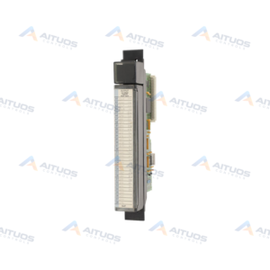
PRODUCT INFORMATION
Product Overview
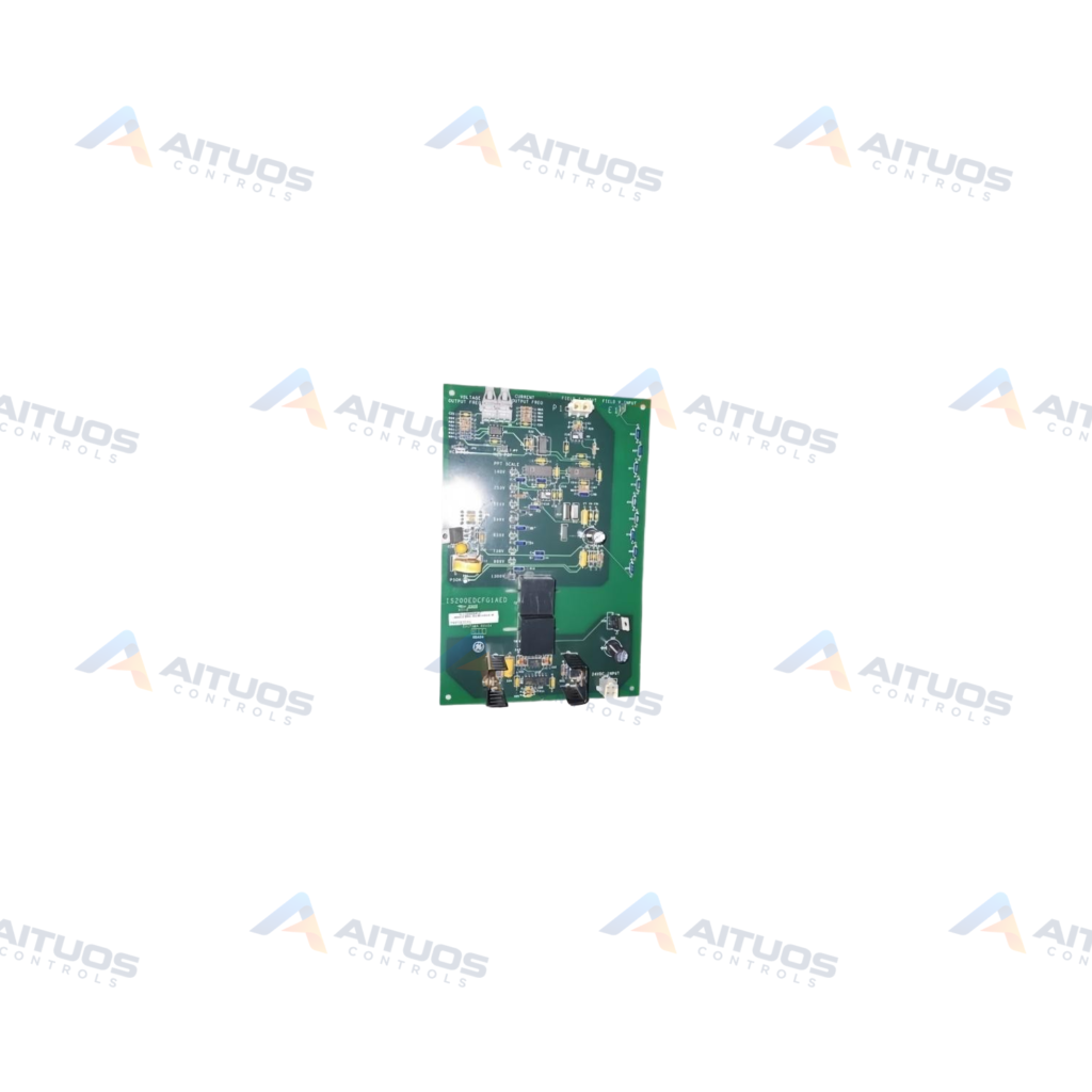
The General Electric IS200EDCFG1AED is a Feedback Board engineered for Mark VI control systems. It measures field current and field voltage at the Silicon Controlled Rectifier bridge. This board operates within gas, steam, and wind turbine automated drive systems. It connects directly with the EISB board located inside the turbine control panel. Voltage isolation on the board is accomplished through dedicated fiber-optic transmission channels. Two optical links provide high electrical noise immunity during operational monitoring. Hard-clad silica optical cabling supports distances up to ninety meters. Plastic fiber cabling supports operational lengths up to ten meters. Seven selector settings allow scaling of the measured bridge feedback voltage.
The IS200EDCFG1AED incorporates two relays, an inductor coil, six integrated circuits, and discrete transistors. Dual heat sinks dissipate thermal loads across the board assembly. External direct current power enters the board via two-pin connector J16. Pin one accepts positive twenty-four volt direct current for the onboard converter. Pin two connects to the common reference line for power conversion. A single status indicator labeled IMOK displays normative operational health. Physical connection points include a two-position plug labeled P1 and a four-position input plug.
TECHNICAL DATA
Technical Specifications
| Parameter | Specification |
|---|
| Instruction Manual | GEI-100464A or GEH-6632 |
|---|
| Functional Acronym/Abbreviation | EDCF |
|---|
| Fiber-Optics Used with the EDCF Board | Plastic or Hard Clad Silica |
|---|
TECHNICAL INFORMATION
Features
- Measures field current and field voltage directly at the exciter SCR bridge.
- Provides optical isolation using hard-clad silica or plastic fiber cabling.
- Features seven voltage feedback selector settings to scale down bridge voltages.
- Includes two onboard relays, an inductor coil, and six integrated circuits.
- Equipped with dual heat sinks for thermal management across electronics.
- Provides visual status feedback using an onboard IMOK functional health indicator.
TECHNICAL INFORMATION
Applications
- Exciter field voltage and current monitoring in Mark VI turbine systems.
- SCR bridge feedback acquisition in steam, gas, and wind turbine drives.
TECHNICAL INFORMATION
Connections / Interfaces
- Connector J16 provides two pins for external positive twenty-four volt power input.
- Pin one on J16 connects to positive twenty-four volts direct current.
- Pin two on J16 provides the common reference for DC-DC conversion.
- Two-position plug P1 facilitates auxiliary circuitry interconnection.
- Four-position input plug receives external exciter feedback wiring.
- Interfaces directly with the EISB board located in the control panel.
TECHNICAL INFORMATION
Installation Guidelines
- Mount the board securely within the turbine control panel enclosure.
- Select optical fiber type based on required transmission distance before routing cables.
- Confirm external twenty-four volt direct current polarity on connector J16 before applying power.
TECHNICAL INFORMATION
Configuration Guidelines
- Configure the seven selector settings to properly scale down bridge feedback voltage.
- Refer to instruction manual GEI-100464A or GEH-6632 for scaling jumper alignment.
TECHNICAL INFORMATION
Compatibility
- Interfaces directly with the Mark VI EISB exciter interface board in the control panel.
- Designed for General Electric Mark VI turbine control system assemblies.
COMPATIBILITY
Compatibility & Replacement
COMPATIBLE MODELSInterfaces directly with the Mark VI EISB exciter interface board in the control panel. Designed for General Electric Mark VI turbine control system assemblies.
Verify compatibility against the exact Part Number, revision and manufacturer documentation before ordering.
PART VERIFICATION
Before You Order
Industrial automation parts can share similar model names, suffixes and revisions. Confirm the complete manufacturer Part Number before purchase.
01Check Part NumberMatch the complete ordering code on the existing unit.
02Confirm RevisionCheck suffix, hardware or firmware when applicable.
03Send a Label PhotoWe can review a clear label photo when identification is uncertain.
ORDERING PROCESS
From RFQ to Dispatch
1Submit Part Number2Verify Product Identity3Confirm Stock & Condition4Issue Quotation5Dispatch & Tracking
PRODUCT FAQ
Frequently Asked Questions
What is the primary function of the IS200EDCFG1AED board?
It measures field current and field voltage at the SCR bridge. It transmits feedback directly to the EISB board.
What fiber-optic cable types work with the IS200EDCFG1AED?
It supports plastic fiber and hard-clad silica fiber. Plastic reaches ten meters, while silica reaches ninety meters.
How is operating power supplied to the IS200EDCFG1AED?
Power connects via connector J16. Pin one receives twenty-four volts direct current, while pin two serves as common.