PRODUCT INFORMATION
Product Overview
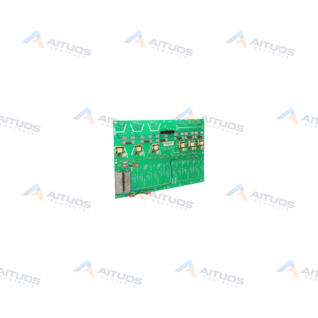
The General Electric DS200PCCAG10ACB is a Mark V Power Connect Card for turbine control and drive systems. This board serves as an interface between the automated drive assembly and the SCR power bridge. It functions within the DC2000 subseries for steam, gas, and wind turbine assemblies. The unit incorporates patented Speedtronic control system architecture developed by General Electric. It represents a group ten hardware design featuring three factory revision levels.
The card supports J-frame and M-frame drive assemblies rated up to 600 V rms maximum AC voltage. Group ten configurations operate with an SDCI power supply board and DC snubber circuits. They also integrate specific leg styles containing both fuses and reactors. Onboard interfaces connect directly to the Mark V DCFB board using eight dedicated connectors. Field technicians configure parameters by connecting a service laptop to the drive serial communication port.
TECHNICAL DATA
Technical Specifications
| Parameter | Specification |
|---|
| Instruction Manual | GEI-100161 |
|---|
| PCB Coating | Normal Coating |
|---|
TECHNICAL INFORMATION
Features
- Interfaces the turbine drive assembly directly to the SCR power bridge.
- Rated for operation with maximum AC line voltage of 600 V rms.
- Features DC snubber circuits specific to group ten Mark V hardware configurations.
- Supports drive integration alongside the SDCI power supply board.
- Includes eight factory-labeled connectors designated for communication with the DCFB board.
- Accommodates leg styles utilizing both protective fuses and reactors.
TECHNICAL INFORMATION
Applications
- General Electric DC2000 automated drive control systems.
- Mark V Speedtronic gas turbine drive management.
- Steam and wind turbine automated drive assemblies.
TECHNICAL INFORMATION
Connections / Interfaces
- Connector 5PL-1 labeled A6F connects the Drive cell 6F gate-pulse transformer.
- Connector 5PL-2 labeled P24 provides +24 volt output.
- Connector 5PL-3 labeled A5F connects the Drive cell 5F gate-pulse transformer.
- Connector 5PL-4 labeled P24 provides +24 volt output.
- Connector 5PL-5 labeled A4F connects the Drive cell 4F gate-pulse transformer.
- Connector 5PL-6 labeled P24 provides +24 volt output.
- Connector 5PL-7 labeled A3F connects the Drive cell 3F gate-pulse transformer.
- Connector 5PL-8 labeled P24 provides +24 volt output.
TECHNICAL INFORMATION
Installation Guidelines
- Disconnect all electrical power to the drive before servicing the card.
- Access the incoming three-phase power supplies providing line current to the drive.
- Remove the input fuses from the power supplies prior to opening enclosures.
- Open the drive bay containing the circuit boards to disconnect existing wiring harnesses.
TECHNICAL INFORMATION
Configuration Guidelines
- Connect a service laptop to the drive using an appropriate serial communication cable.
- Verify that the laptop serial port settings match drive communication parameters.
- Initiate parameter file download commands from the drive control panel.
- Verify that the control panel displays a completion message after file transfer.
- Use editing software to inspect diagnostic logs and modify operational parameters.
- Upload the modified parameter file back to the drive control panel.
TECHNICAL INFORMATION
Compatibility
- Compatible with General Electric Mark V DC2000 drive systems.
- Engineered for J-frame and M-frame drive enclosures.
- Operates with the SDCI power supply board.
- Directly links to the Mark V DCFB printed circuit board.
TECHNICAL INFORMATION
Lifecycle / Replacement Information
- The DS200PCCAG10ACB updates the earlier parent DS200PCCAG10 board with three revision stages.
COMPATIBILITY
Compatibility & Replacement
COMPATIBLE MODELSCompatible with General Electric Mark V DC2000 drive systems. Engineered for J-frame and M-frame drive enclosures. Operates with the SDCI power supply board. Directly links to the Mark V DCFB printed circuit board.
Verify compatibility against the exact Part Number, revision and manufacturer documentation before ordering.
PART VERIFICATION
Before You Order
Industrial automation parts can share similar model names, suffixes and revisions. Confirm the complete manufacturer Part Number before purchase.
01Check Part NumberMatch the complete ordering code on the existing unit.
02Confirm RevisionCheck suffix, hardware or firmware when applicable.
03Send a Label PhotoWe can review a clear label photo when identification is uncertain.
ORDERING PROCESS
From RFQ to Dispatch
1Submit Part Number2Verify Product Identity3Confirm Stock & Condition4Issue Quotation5Dispatch & Tracking
PRODUCT FAQ
Frequently Asked Questions
What primary function does the GE DS200PCCAG10ACB card perform?
The board interfaces the automated drive system with the SCR power bridge. It serves DC2000 Mark V turbine drive assemblies.
What voltage rating applies to the DS200PCCAG10ACB board?
The DS200PCCAG10ACB card supports a maximum AC voltage rating of 600 V rms. It is configured specifically for J-frame and M-frame hardware.
How are drive configuration parameters transferred during maintenance?
Engineers connect a configured laptop to the drive using a serial cable. Commands on the drive control panel initiate download and upload procedures.
What is the reference price for the DS200PCCAG10ACB board?
Pricing varies based on unit condition, inventory availability, and testing standards. All listed pricing figures represent indicative market reference pricing only and are not a final quotation.