PRODUCT INFORMATION
Product Overview
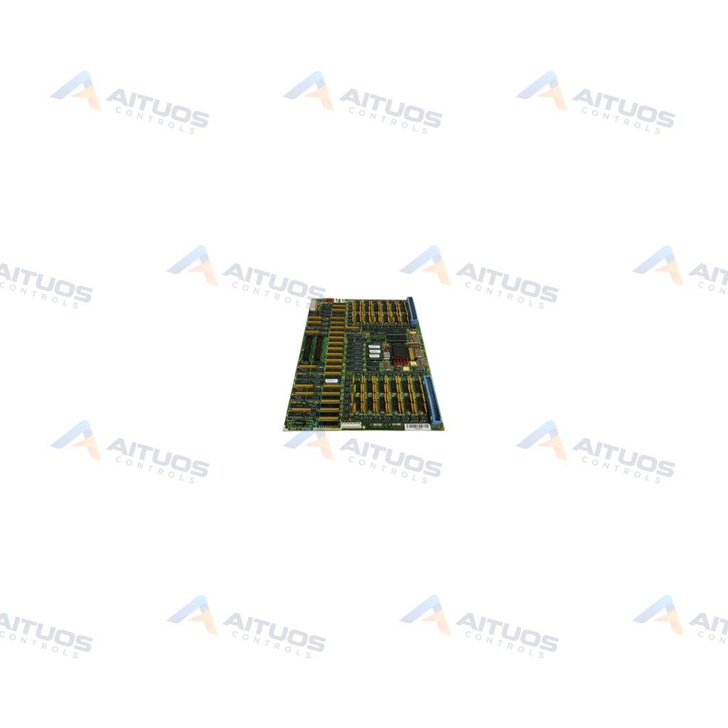
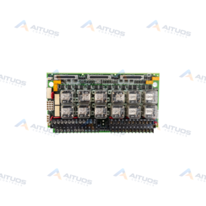
The General Electric DS200TCDAG1ADA is a Digital I/O Board manufactured for Speedtronic Mark V turbine control systems. This circuit board modifies the parent DS200TCDAG1 hardware design through three distinct factory revision levels. It incorporates one microprocessor alongside multiple programmable read-only memory modules for local processing. A dedicated block of ten status LED indicators provides visual feedback for operational monitoring.
Hardware connectivity centers on two 50-pin ribbon cable headers labeled JQ and JR on the board surface. The circuit board assembly includes up to eight configurable three-pin jumpers for hardware signal path selection. A side-facing LED indicator allows status viewing when the card sits in a control rack. Standard normal coating protects the printed circuit board assembly against typical operating environments.
TECHNICAL DATA
Technical Specifications
| Parameter | Specification |
|---|
| PCB Coating | Normal Coating |
|---|
TECHNICAL INFORMATION
Features
- Operates using a single onboard microprocessor architecture.
- Incorporates multiple socketed programmable read-only memory modules.
- Features a ten-LED diagnostic block for operational status verification.
- Includes one additional side-visible LED for rack-level inspection.
- Equipped with up to eight three-pin jumpers for signal routing.
- Provides two distinct 50-pin ribbon connectors designated JQ and JR.
- Manufactured with normal protective printed circuit board coating.
TECHNICAL INFORMATION
Applications
- General Electric Speedtronic Mark V turbine control panels.
- Digital input and output interfacing in industrial gas and steam turbine systems.
TECHNICAL INFORMATION
Connections / Interfaces
- JQ: 50-pin header for ribbon cable digital interface connection.
- JR: 50-pin header for secondary ribbon cable interface connection.
TECHNICAL INFORMATION
Installation Guidelines
- Confirm that the host Mark V turbine control system is completely de-energized.
- Verify connector designations JQ and JR on the board surface prior to cabling.
- Align the flat ribbon cables carefully with header pins to prevent mechanical pin damage.
TECHNICAL INFORMATION
Configuration Guidelines
- Inspect the position of up to eight jumper blocks before placing the board into service.
- Set each jumper across pins 1 and 2 or pins 2 and 3 as required.
- Connecting pins 1 and 2 leaves pin 3 isolated from that signal circuit.
- Ensure installed PROM modules match the software revision requirements of your system.
TECHNICAL INFORMATION
Compatibility
- Compatible with General Electric Mark V Speedtronic turbine control architectures.
- Interchanges with earlier DS200TCDAG1 revisions when jumper and cable routing match.
TECHNICAL INFORMATION
Lifecycle / Replacement Information
- Board layout revisions may reposition connectors while retaining identical JQ and JR designations.
- Match jumper positions on replacement units to those on the original board before commissioning.
COMPATIBILITY
Compatibility & Replacement
COMPATIBLE MODELSCompatible with General Electric Mark V Speedtronic turbine control architectures. Interchanges with earlier DS200TCDAG1 revisions when jumper and cable routing match.
Verify compatibility against the exact Part Number, revision and manufacturer documentation before ordering.
PART VERIFICATION
Before You Order
Industrial automation parts can share similar model names, suffixes and revisions. Confirm the complete manufacturer Part Number before purchase.
01Check Part NumberMatch the complete ordering code on the existing unit.
02Confirm RevisionCheck suffix, hardware or firmware when applicable.
03Send a Label PhotoWe can review a clear label photo when identification is uncertain.
ORDERING PROCESS
From RFQ to Dispatch
1Submit Part Number2Verify Product Identity3Confirm Stock & Condition4Issue Quotation5Dispatch & Tracking
PRODUCT FAQ
Frequently Asked Questions
What is the function of the General Electric DS200TCDAG1ADA?
The board provides digital input and output processing within General Electric Speedtronic Mark V turbine control panels.
What ribbon cable connectors are present on the DS200TCDAG1ADA?
The board features two 50-pin ribbon connectors clearly marked JQ and JR on the surface.
How are the configurable jumpers set on the DS200TCDAG1ADA board?
Jumpers bridge pins 1 and 2 or pins 2 and 3 to establish designated signal paths.
How can technicians observe onboard operational status on the DS200TCDAG1ADA?
Technicians can monitor an integrated ten-LED block as well as a side-mounted diagnostic LED.