

Bently Nevada Proximity Sensor Setup: 3300 XL Field Guide
Bently Nevada proximity sensor setup depends on three things being correct at the same time: the matched transducer system, the probe gap, and the receiving instrumentation. The probe, extension cable, and Proximitor sensor should be treated as one calibrated measurement chain rather than as interchangeable field devices.
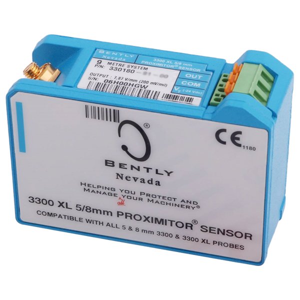
This guide focuses on the 3300 XL 8 mm system and the commonly encountered 330180 Proximitor sensor. It also explains where larger systems, such as the 3300 XL 25 mm transducer system, differ. Always verify the exact Baker Hughes datasheet for the installed model before applying a gap voltage or scaling value.
What the Bently Nevada Proximity System Actually Measures
Bently Nevada proximity transducer systems use an eddy-current principle to measure the distance between a probe tip and a conductive target, typically a rotating shaft. The DC component of the Proximitor output represents probe-to-target gap. Dynamic changes in that voltage represent shaft vibration or motion.
Depending on the monitoring application, the same basic measurement principle is used for radial vibration, axial or thrust position, Keyphasor or speed references, differential expansion, and other turbine supervisory measurements.
Understand the Complete Measurement Chain
A typical Bently Nevada proximity measurement chain contains:
- A proximity probe installed near the machine shaft or target.
- An extension cable when required by the selected system length.
- A Proximitor sensor that powers the probe and conditions the signal.
- Field wiring from the Proximitor sensor to a machinery monitor or compatible receiving device.
- A monitoring or control system that interprets the static and dynamic signal.
The probe, extension cable, and Proximitor sensor are calibrated as a system. Changing system length or mixing incompatible components can alter scale factor, linearity, and usable range.
330180-51-05: What the Ordering Code Tells You
The 330180 family is the 3300 XL Proximitor sensor used with 5 mm and 8 mm Bently Nevada proximity probes. In the 330180 ordering structure, the option code identifies total system length and mounting arrangement, while the final approval code identifies agency approvals.
For the commonly encountered 330180-51-05 configuration, the system is a 5.0 metre 3300 XL arrangement using DIN-rail mounting with multiple agency approvals. The exact installed probe and extension cable must still be checked before commissioning.
Power Supply: Why a Normal +24 VDC Loop Is Not the Same Thing
The 3300 XL 8 mm Proximitor sensor is specified for a negative DC supply. Baker Hughes documentation specifies approximately -17.5 VDC to -26 VDC without barriers, with maximum current consumption around 12 mA. Barrier applications have a narrower permitted supply range.
The important reference is the Proximitor COM terminal. The supply terminal is negative relative to COM. Therefore, simply connecting the device as if it were a standard positive 24 V transmitter is incorrect.
In many machinery protection installations, the cleaner solution is to use the intended Bently Nevada monitor or a purpose-designed interface. If a PLC must receive the signal directly, confirm that the analog input and signal-conditioning arrangement can safely accept the Proximitor’s negative DC output and required common reference.
3300 XL 8 mm Gap and Scale Values
For the standard 3300 XL 8 mm proximity system, Baker Hughes specifies a linear range of approximately 0.25 to 2.3 mm (10 to 90 mils). Over this range, output is approximately -1 to -17 VDC.
The standard incremental scale factor is 7.87 V/mm (200 mV/mil). For radial vibration applications, the datasheet gives a recommended gap setting of approximately -9 VDC, corresponding to about 1.27 mm (50 mils).
| 3300 XL 8 mm parameter | Typical value | Practical meaning |
|---|---|---|
| Linear range | 0.25–2.3 mm (10–90 mils) | Use the probe within this calibrated region. |
| Output over linear range | Approx. -1 to -17 VDC | Gap voltage becomes more negative as distance changes through the calibrated range. |
| Scale factor | 7.87 V/mm (200 mV/mil) | Used for displacement and vibration scaling. |
| Recommended radial gap | Approx. -9 VDC | Places the probe near the middle of its linear range. |
| Approximate physical gap | 1.27 mm (50 mils) | Typical radial setup point for the 8 mm system. |
These values apply to the 3300 XL 8 mm family. Do not transfer them to a 25 mm or 50 mm turbine proximity system.
Step-by-Step Radial Probe Setup
- Identify every component. Record probe part number, extension cable part number, Proximitor part number, and total system length.
- Verify compatibility. Confirm the three components belong to the same calibrated system family and length.
- Inspect the target surface. The shaft surface should be suitable for eddy-current measurement and free from damage where the probe observes it.
- Confirm wiring. Verify supply, COM, and OUT at the Proximitor before energizing.
- Power the system with the correct negative supply. Confirm voltage between Vt and COM at the actual Proximitor terminals.
- Measure DC gap voltage. Connect the measuring instrument between OUT and COM.
- Adjust probe position slowly. Move the probe until the correct gap voltage is reached.
- Lock the probe mechanically. Recheck gap voltage after tightening because the final mechanical position can move slightly.
- Verify dynamic response. Confirm the machinery monitor or receiving system sees a stable, correctly scaled signal.
Radial Vibration: Why Mid-Range Gap Matters
For radial vibration, the shaft moves both toward and away from the probe as it rotates. A mid-range static gap gives the transducer useful measurement travel in both directions.
This is why the 3300 XL 8 mm datasheet recommends about -9 VDC for radial vibration. The value is not an arbitrary zero point. It positions the operating point near the middle of the calibrated linear range so dynamic shaft motion can be measured without driving the sensor toward either end of its range.
Axial or Thrust Position Requires a Different Setup Decision
Axial position is different from radial vibration because the engineering zero depends on the machine’s thrust geometry and protection philosophy. Some installations reference the active thrust position. Others center the electrical range around the expected shaft travel.
A field technique discussed by experienced users is to move the shaft through its known axial travel, observe the corresponding DC voltage change, and position the probe so the desired mechanical reference lies at the required electrical point. That method should only be used when the machine’s thrust limits, active/inactive directions, and alarm philosophy are already defined.
Can the Proximitor Output Go Directly to a PLC?
Sometimes, but not to just any analog input.
The 3300 XL Proximitor output contains both static gap information and dynamic vibration information. Its signal is a negative voltage referenced to COM. A standard PLC input configured for 0–10 VDC or 4–20 mA may not accept that signal directly.
Before direct PLC integration, verify all of the following:
- The PLC analog input supports the required negative voltage range.
- The PLC common can be referenced correctly without creating a ground loop.
- The signal bandwidth is adequate for the measurement objective.
- The input will not clamp or damage the Proximitor output.
- Required galvanic isolation or signal conditioning is provided.
- Hazardous-area barriers are included where required.
For machinery protection, a dedicated Bently Nevada monitor is generally a better architecture because it handles transducer power, signal processing, alarm logic, diagnostics, and retransmission in a controlled system. A PLC can then receive a conditioned or retransmitted value rather than the raw proximity signal.
For readers working with rack-based protection hardware, see the Bently Nevada 3500 System technical series page for related monitoring architecture.
Do Not Apply 8 mm Values to the 25 mm System
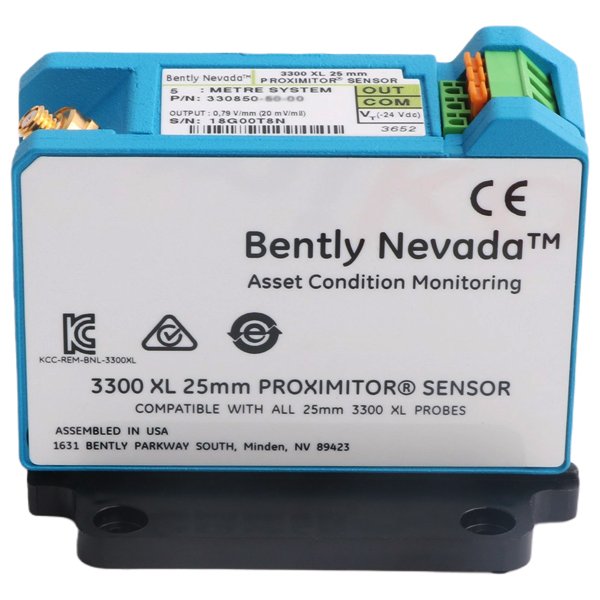
The larger 3300 XL 25 mm transducer system is intended primarily for turbine supervisory measurements such as differential expansion. Baker Hughes specifies an extended linear measurement range of 12.7 mm (500 mils) for this system.
The 25 mm system also uses a different output scale from the 8 mm family. Therefore, the -9 VDC radial setup value and 7.87 V/mm scale factor discussed above should not be assumed for a 25 mm installation.
This is a common source of field mistakes: the housings may look similar, but the calibration and intended application can be very different.
Common Setup Errors
- Mixing a probe, extension cable, and Proximitor from different system lengths.
- Assuming all Bently Nevada proximity systems use the same scale factor.
- Using a conventional positive analog input without checking negative-voltage capability.
- Setting the gap by physical distance only and never checking DC output.
- Adjusting the probe before verifying the machine’s actual mechanical reference.
- Failing to recheck gap voltage after tightening the probe locknut.
- Routing field wiring beside high-power or high-noise cables.
- Ignoring shield grounding or barrier requirements.
- Using a machinery-protection channel as if it were only a slow process signal.
Practical Troubleshooting
No Output or Output Stuck Near the Supply Rail
Check power polarity and voltage at Vt-to-COM, then verify the probe and extension cable connections. Also confirm that the probe target is within a reasonable distance.
Gap Voltage Looks Correct but PLC Value Is Wrong
Check analog input range, common reference, engineering-unit scaling, and whether the input accepts a bipolar or negative signal. A correct Proximitor output does not guarantee a standard PLC card can interpret it.
Signal Is Noisy
Inspect probe mounting stiffness, shield termination, field wiring route, grounding, and nearby VFD or motor cables. Also confirm the probe cable and extension cable connectors are clean and fully engaged.
Static Gap Is Stable but Vibration Reading Is Incorrect
Check the configured scale factor, monitor channel type, frequency response, target material, and whether the installed probe family matches the configured transducer type.
Commissioning Checklist
- Exact probe part number recorded
- Exact extension cable part number recorded
- Exact Proximitor part number recorded
- Total system length verified
- Supply voltage checked at the Proximitor terminals
- COM and signal reference verified
- Static gap voltage recorded
- Mechanical locknut secured
- Gap voltage rechecked after tightening
- Receiving channel scale factor verified
- Alarm and shutdown logic checked where applicable
- Final commissioning values saved in maintenance records
FAQ
What voltage should a Bently Nevada 3300 XL 8 mm probe be gapped to?
For standard radial vibration applications, Baker Hughes specifies a recommended gap of approximately -9 VDC, corresponding to about 1.27 mm (50 mils). Verify the exact datasheet and application before adjustment.
What is the 3300 XL 8 mm scale factor?
The standard incremental scale factor is 7.87 V/mm (200 mV/mil) over the specified linear range.
What power supply does a 330180 Proximitor use?
The standard 3300 XL 8 mm Proximitor requires a negative DC supply. Baker Hughes specifies approximately -17.5 to -26 VDC without barriers, with different requirements when barriers are used.
Can a 330180 Proximitor connect directly to a PLC analog input?
Only when the PLC input and grounding arrangement are designed for the Proximitor’s negative voltage signal. Many conventional 0–10 V or 4–20 mA cards are not suitable without signal conditioning or an appropriate interface.
Do Bently Nevada probes, extension cables, and Proximitor sensors have to match?
Yes. They are calibrated as a transducer system. The family and total system length must match the intended configuration.
Is the 3300 XL 25 mm system set up the same way as the 8 mm system?
No. The 25 mm system has a much larger measurement range and a different scale factor. Use the 25 mm datasheet rather than applying 8 mm setup values.
Technical Sources
Primary OEM references: Baker Hughes / Bently Nevada proximity sensor portfolio and the 3300 XL 8 mm and 25 mm Proximity Transducer System datasheets.
Field discussion: How to Setup Bently Nevada Proximity Sensors, Control.com Automation & Control Engineering Forum. The thread was started by msohaibbutt on September 29, 2018. Forum comments were treated as field experience and were cross-checked against OEM specifications before inclusion.
OEM product information: Bently Nevada Proximity Probes, Sensors & Transducer Systems.
OEM 8 mm datasheet: 3300 XL 8 mm Proximity Transducer System Datasheet 141194.
OEM 25 mm datasheet: 3300 XL 25 mm Proximity Transducer System Datasheet 163236.