PRODUCT INFORMATION
Product Overview
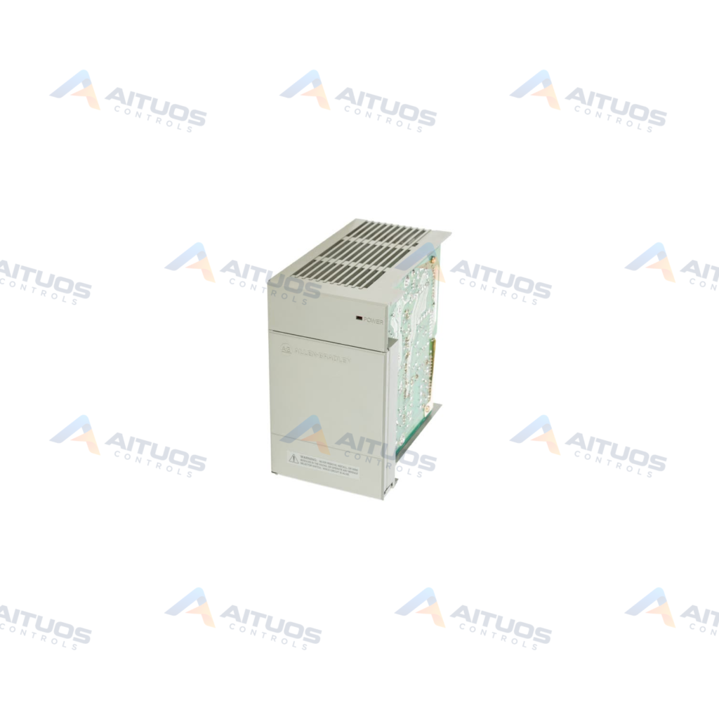
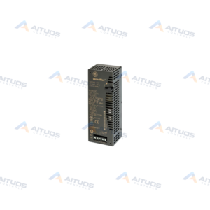
The Allen-Bradley 1746-P3 is a dedicated Power Supply module designed for the SLC 500 controller platform. It mounts directly at the leftmost position of a 1746 chassis without occupying a standard slot. The unit converts a 24V DC nominal input supply into internal backplane operating voltages. It delivers backplane current capacities of 3.6 A at 5V DC and 0.87 A at 24V DC.
This power supply accepts an operational DC input range spanning 19.2 to 28.8V DC. It features a typical line power requirement of 90 VA and nominal input power of 61 Watts. CPU hold-up times reach 5 ms at full load and extend up to 1000 ms at zero load. Internal protection includes an integrated fuse replaceable with an Allen-Bradley 1746-F3 or approved equivalent.
TECHNICAL DATA
Technical Specifications
| Parameter | Specification |
|---|
| Backplane Current (24 Volts) | 0.87 Amps |
|---|
| Backplane Current (5 Volts) | 3.6 Amps |
|---|
| Category | PLCs |
|---|
| Current Capacity | 3.6 A at 5V dc and 0.87 A at 24V dc |
|---|
| Current capacity deration | 5% above 55 °C (131 °F). |
|---|
| Frequency | DC |
|---|
| Fuse protection | 1746-F3 or equivalent |
|---|
| GTIN | 10662073521430 |
|---|
| Hold Up time | 5 ms (full load); 1000 ms (no load) |
|---|
| Input Power | 61 Watts |
|---|
| Input Voltage | 24 Volts DC |
|---|
| Input Voltage Range | 19.2-28.8 VDC |
|---|
| Inrush Current | 20 A |
|---|
| Isolation Voltage | 600V ac RMS for 1 s (version B or later) |
|---|
| Location | 1746 Chassis, Left Side |
|---|
| Module Type | Power Supply |
|---|
| Nom Input Voltage | 24VDC |
|---|
| Operating Temperature | 0 to 60 degrees Celsius |
|---|
| Temperature, ambient operating | 0...60 °C (32...140 °F) |
|---|
| Typical line power requirement | 90 VA |
|---|
| UPC | 10662073521430 |
|---|
| Weight | 1.31 lbs (0.60 kg) |
|---|
TECHNICAL INFORMATION
Features
- Mounts on the left side of the 1746 rack without taking up an I/O module slot.
- Accepts a wide direct-current input voltage range between 19.2V DC and 28.8V DC.
- Provides backplane power delivery of 3.6 Amps at 5V DC and 0.87 Amps at 24V DC.
- Offers CPU hold-up performance of 5 ms at full load and 1000 ms under zero load.
- Provides 600V AC RMS dielectric withstand between chassis ground and input terminals for 1 second.
- Contains field-replaceable fuse protection compatible with 1746-F3, BUSSMAN AGC 5, or Nagasawa ULCS-61ML-5 units.
TECHNICAL INFORMATION
Applications
- SLC 500 modular chassis automation racks operating on primary 24V DC control power.
- Industrial control enclosures located in Class 1, Division 2 hazardous environments.
- Factory control systems requiring backplane power distribution for local I/O modules.
TECHNICAL INFORMATION
Connections / Interfaces
- Direct chassis left-side connection interface supplying the 1746 backplane bus.
- Screw terminal connections supporting direct 24V DC nominal field input power wiring.
- Chassis ground screw terminal providing protective earth bonding for dielectric isolation.
TECHNICAL INFORMATION
Installation Guidelines
- Install the unit exclusively into the dedicated power supply location on the left side of the chassis.
- Use a 1/8-inch flat head or 1/4-inch Phillips screwdriver to secure mounting screws.
- Maintain electro-static discharge protection by storing the module in static-shield packaging until final hardware installation.
- Avoid touching exposed connector pins, backplane connectors, and printed circuit board components.
- Derate backplane current capacity by 5 percent when ambient operating temperatures exceed 55 degrees Celsius.
TECHNICAL INFORMATION
Configuration Guidelines
- Verify total module load does not exceed 3.6 A at 5V DC and 0.87 A at 24V DC.
- Confirm that incoming power supply feed stays within the 19.2 to 28.8V DC range.
- Select appropriate external branch circuit fusing matching wire gauge limitations and end-device requirements.
TECHNICAL INFORMATION
Compatibility
- Allen-Bradley SLC 500 modular hardware platforms.
- Allen-Bradley 1746 modular chassis backplanes.
- Replacement fuse units including 1746-F3, BUSSMAN AGC 5, and Nagasawa ULCS-61ML-5.
TECHNICAL INFORMATION
Lifecycle / Replacement Information
- Use only approved replacement fuses to prevent damage to internal DC power conversion stages.
- Verify chassis slot clearance before replacing older SLC 500 power supply models.
TECHNICAL INFORMATION
Compliance and Certifications
- UL Listed as Industrial Control Equipment for Class 1, Division 2, Groups A, B, C, D.
- C-UL Listed as Industrial Control Equipment for Class 1, Division 2, Groups A, B, C, D.
- Rated for Category II installations and Pollution Degree 2 operating environments.
COMPATIBILITY
Compatibility & Replacement
COMPATIBLE MODELSAllen-Bradley SLC 500 modular hardware platforms. Allen-Bradley 1746 modular chassis backplanes. Replacement fuse units including 1746-F3, BUSSMAN AGC 5, and Nagasawa ULCS-61ML-5.
Verify compatibility against the exact Part Number, revision and manufacturer documentation before ordering.
PART VERIFICATION
Before You Order
Industrial automation parts can share similar model names, suffixes and revisions. Confirm the complete manufacturer Part Number before purchase.
01Check Part NumberMatch the complete ordering code on the existing unit.
02Confirm RevisionCheck suffix, hardware or firmware when applicable.
03Send a Label PhotoWe can review a clear label photo when identification is uncertain.
ORDERING PROCESS
From RFQ to Dispatch
1Submit Part Number2Verify Product Identity3Confirm Stock & Condition4Issue Quotation5Dispatch & Tracking
PRODUCT FAQ
Frequently Asked Questions
Does the 1746-P3 power supply consume an I/O slot in the SLC 500 chassis?
No. The 1746-P3 installs on the far left side of the chassis without using an I/O slot.
What input voltage does the Allen-Bradley 1746-P3 require?
It requires a nominal 24V DC input with an acceptable operational range of 19.2 to 28.8V DC.
Which replacement fuses are compatible with the 1746-P3?
Use the Allen-Bradley 1746-F3 fuse or approved equivalents such as BUSSMAN AGC 5 and Nagasawa ULCS-61ML-5.