PRODUCT INFORMATION
Product Overview
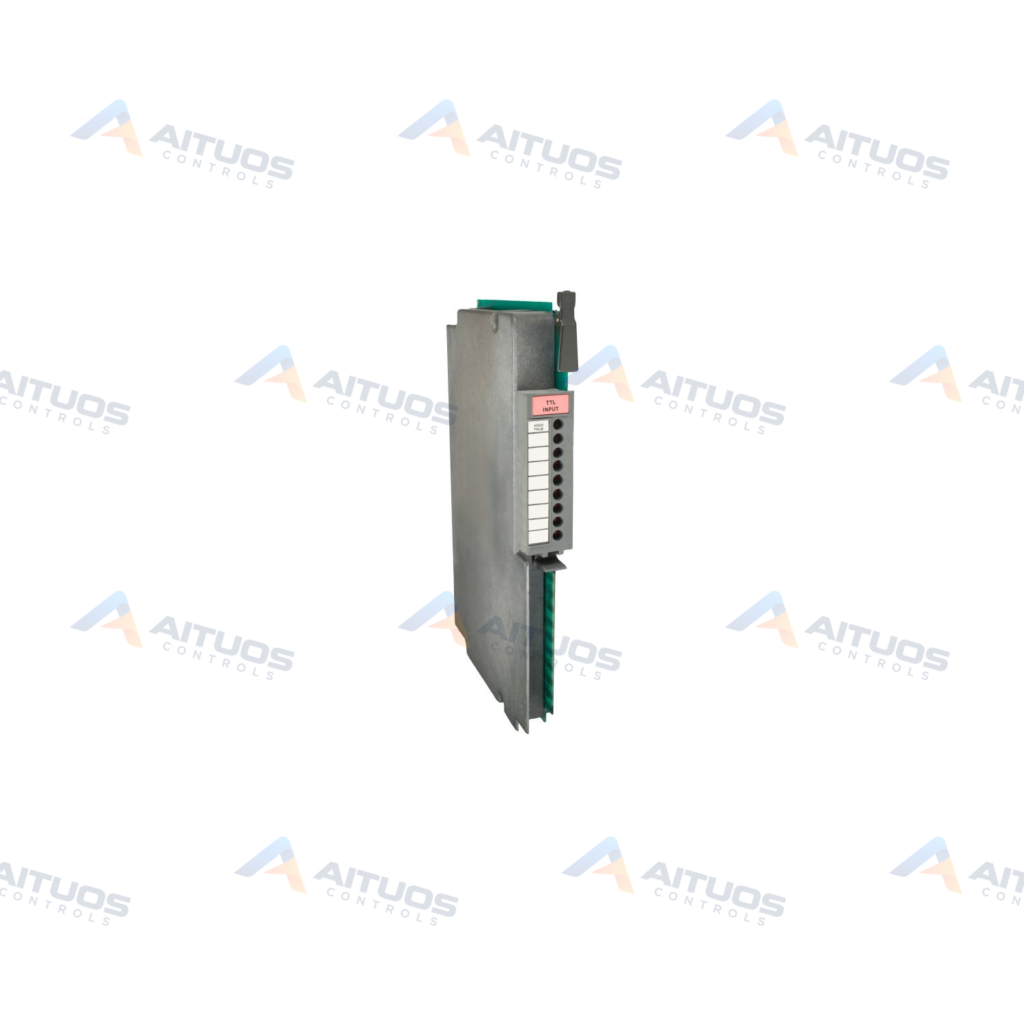
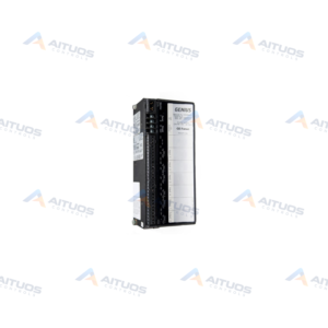
The Allen-Bradley 1771-IGC is a PLC-5 TTL Input Module designed for industrial logic processing. This unit converts external direct-current signals into processor-compatible logic levels. It directly updates corresponding bit states within the controller data table. The hardware features eight discrete input circuits supporting five-volt direct-current TTL voltage standards.
A 1771-WC wiring arm attaches to the chassis to simplify module replacement. This design eliminates the requirement to disconnect field signal wiring during maintenance. Internal optoelectrical isolation protects system circuitry from transient electrical noise and surges. Front panel indicators display active input status for immediate diagnostic feedback.
TECHNICAL DATA
Technical Specifications
| Parameter | Specification |
|---|
| Backplane Current | 122 Miliamperes |
|---|
| Category | PLCs |
|---|
| DC Operating Voltage | 5.0-5.3 Volts |
|---|
| Model Status | Earlier Model |
|---|
| Module Type | Digital DC Input Module |
|---|
| Number of Inputs | 8 Inputs |
|---|
| Product Line | PLC 5 |
|---|
| Typical AC Signal Delay (Off) | 24 (+/- 10) ms |
|---|
| Typical DC Signal Delay (Off) | 20 (+/- 9) ms |
|---|
| Typical DC Signal Delay (On) | < 1 ms |
|---|
| Voltage Category | 5 Volts DC, TTL |
|---|
| Weight | 0.81 lbs (0.37 kg) |
|---|
| Wiring Arm | 1771-WC |
|---|
TECHNICAL INFORMATION
Features
- Provides eight discrete TTL-compatible input channels.
- Supports selectable High-True or Low-True logic operation via internal switches.
- Features optoelectrical isolation to safeguard internal backplane circuits.
- Includes eight front-panel status indicators for visual signal verification.
- Uses a 1771-WC wiring arm for rapid removal and insertion under maintenance.
TECHNICAL INFORMATION
Applications
- Interfacing with TTL logic level circuits and solid-state sensors.
- Binary Coded Decimal encoder signal monitoring in manufacturing systems.
- High-speed digital signal acquisition in PLC-5 automation architectures.
TECHNICAL INFORMATION
Connections / Interfaces
- Field wiring terminates via the external 1771-WC wiring arm.
- Backplane connection establishes via 1771 I/O chassis backplane edge connectors.
- Upper connector keying bands locate between pins 34 and 36.
- Lower connector keying bands locate between pins 4 and 6.
TECHNICAL INFORMATION
Installation Guidelines
- Insert the module into an assigned slot in a 1771 I/O chassis.
- Position chassis keying bands properly before sliding the module into place.
- Secure the 1771-WC wiring arm onto the chassis pivot pins.
- Ensure backplane power capacity accommodates the 122 mA load rating.
TECHNICAL INFORMATION
Configuration Guidelines
- Select High-True or Low-True logic mode using onboard configuration switches.
- Assign module addresses using 1/2-slot, 1-slot, or 2-slot addressing modes.
- Map the eight input bits to the designated PLC-5 input image table.
TECHNICAL INFORMATION
Compatibility
- Compatible with Allen-Bradley 1771 I/O chassis.
- Integrates into Allen-Bradley PLC-5 control systems.
- Requires the 1771-WC wiring arm for field connection.
TECHNICAL INFORMATION
Lifecycle / Replacement Information
- The 1771-IGC is an earlier model sharing operational specifications with the 1771-IG module.
TECHNICAL RESOURCES
Documentation
COMPATIBILITY
Compatibility & Replacement
COMPATIBLE MODELSCompatible with Allen-Bradley 1771 I/O chassis. Integrates into Allen-Bradley PLC-5 control systems. Requires the 1771-WC wiring arm for field connection.
Verify compatibility against the exact Part Number, revision and manufacturer documentation before ordering.
PART VERIFICATION
Before You Order
Industrial automation parts can share similar model names, suffixes and revisions. Confirm the complete manufacturer Part Number before purchase.
01Check Part NumberMatch the complete ordering code on the existing unit.
02Confirm RevisionCheck suffix, hardware or firmware when applicable.
03Send a Label PhotoWe can review a clear label photo when identification is uncertain.
ORDERING PROCESS
From RFQ to Dispatch
1Submit Part Number2Verify Product Identity3Confirm Stock & Condition4Issue Quotation5Dispatch & Tracking
PRODUCT FAQ
Frequently Asked Questions
What is the operating voltage of the Allen-Bradley 1771-IGC?
The 1771-IGC module operates across a voltage range of 5.0 to 5.3 V DC TTL.
Which wiring arm is compatible with the 1771-IGC module?
The 1771-IGC requires the Allen-Bradley 1771-WC removable wiring arm for field terminations.
What are the slot keying pin locations for the 1771-IGC?
Keying bands mount between pins 34 and 36 on the upper connector, and pins 4 and 6 below.
What addressing modes does the 1771-IGC support?
The module supports 1/2-slot, 1-slot, and 2-slot I/O addressing within compatible 1771 chassis.