PRODUCT INFORMATION
Product Overview
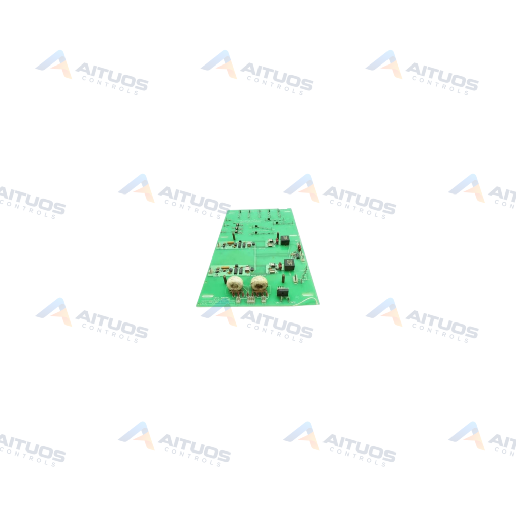
The General Electric DS200SHVIG1BGD is an SCR High Voltage Interface Board designed for Mark V control systems. This circuit board interfaces between the system silicon-controlled rectifier bridge and the power supply. It provides signal conversion across GE gas, steam, and wind turbine automated drive assemblies. The unit features a triple revision level consisting of revisions B, G, and D.
This interface card processes millivolt input signals ranging from minus 500 mV to positive 500 mV. The board converts these input voltages into differential frequency outputs between 0 and 500 kHz. The drive power supply receives these converted frequencies for system monitoring and drive regulation. Onboard circuits include normal protective coating and voltage suppression networks.
TECHNICAL DATA
Technical Specifications
| Parameter | Specification |
|---|
| Instruction Manual | GEI-100160 |
|---|
| PCB Coating | Normal Coating |
|---|
TECHNICAL INFORMATION
Features
- Converts input signals from minus 500 mV to positive 500 mV into differential frequencies.
- Generates output frequency signals ranging from 0 to 500 kHz for the power supply.
- Equipped with seventeen user-configurable jumpers for circuit attenuation.
- Features 10 to 1 ratio current transformers across configuration jumpers.
- Includes three onboard LED indicators to signal blown filter fuses.
- Incorporates voltage suppression networks with capacitors, resistors, and diodes.
TECHNICAL INFORMATION
Applications
- General Electric Mark V Speedtronic turbine control systems.
- GE-compatible gas turbine drive control assemblies.
- Steam turbine management systems using Mark V hardware.
- Automated wind turbine drive assemblies.
TECHNICAL INFORMATION
Connections / Interfaces
- Interfaces directly between the system SCR bridge and the drive power supply.
- Communicates operational signals with the Power Connect Card.
- Exchanges diagnostic and operational signals with the drive instrumentation card.
TECHNICAL INFORMATION
Installation Guidelines
- Ensure all power to the drive assembly is disconnected before servicing.
- Handle using proper electrostatic discharge precautions to prevent board damage.
- Only qualified personnel familiar with high-voltage drive hardware should perform installation.
- Consult instruction manual GEI-100160 for complete wiring and mounting instructions.
TECHNICAL INFORMATION
Configuration Guidelines
- Configure the seventeen onboard jumpers to match site attenuation requirements.
- Verify jumper positions prior to applying power to the drive assembly.
TECHNICAL INFORMATION
Compatibility
- Compatible with General Electric Mark V Speedtronic turbine control drives.
- Interfaces with GE Power Connect Cards and associated instrumentation boards.
TECHNICAL INFORMATION
Lifecycle / Replacement Information
- Serves as an upgraded revision variant of parent board DS200SHVIG1.
- Incorporates revision B functional, revision G functional, and revision D artwork changes.
COMPATIBILITY
Compatibility & Replacement
COMPATIBLE MODELSCompatible with General Electric Mark V Speedtronic turbine control drives. Interfaces with GE Power Connect Cards and associated instrumentation boards.
Verify compatibility against the exact Part Number, revision and manufacturer documentation before ordering.
PART VERIFICATION
Before You Order
Industrial automation parts can share similar model names, suffixes and revisions. Confirm the complete manufacturer Part Number before purchase.
01Check Part NumberMatch the complete ordering code on the existing unit.
02Confirm RevisionCheck suffix, hardware or firmware when applicable.
03Send a Label PhotoWe can review a clear label photo when identification is uncertain.
ORDERING PROCESS
From RFQ to Dispatch
1Submit Part Number2Verify Product Identity3Confirm Stock & Condition4Issue Quotation5Dispatch & Tracking
PRODUCT FAQ
Frequently Asked Questions
What is the primary function of the DS200SHVIG1BGD interface board?
The board interfaces between the SCR bridge and power supply while converting millivolt signals into frequencies.
What input voltage range does the DS200SHVIG1BGD accept?
The card accepts and processes voltage signals ranging between minus 500 mV and positive 500 mV.
How are blown filter fuses identified on the board?
Three onboard LED indicator lights illuminate to visually alert operators when filter fuses blow.
What documentation covers installation of the DS200SHVIG1BGD?
Installation and wiring details are specified in General Electric instruction manual GEI-100160.
What is the reference price for the DS200SHVIG1BGD board?
Pricing is subject to stock and condition. Published figures are indicative market reference pricing only and not a final quotation.