PRODUCT INFORMATION
Product Overview
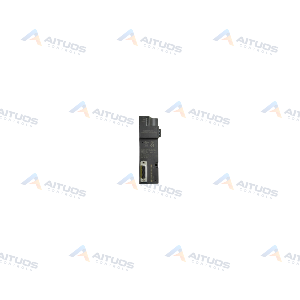
The General Electric IC200ETM001 is a VersaMax expansion connector module designed for PLC system expansion. It mounts directly on a DIN rail on the left side of the CPU or Network Interface Unit. The module expands the system architecture by connecting to downstream expansion receiver modules across external racks. It supports system expansion of up to seven additional racks. Each additional rack accommodates up to eight input and output modules, including field-bus communication units.
This expansion module receives 5 VDC power directly from the host CPU or Network Interface Unit. It features a 26-pin female front connector for expansion interface cabling to receiver modules. A 16-pin male serial port located at the upper left corner facilitates firmware updates for adjacent NIU hardware. Two status LED indicators display power availability and transmission status across the bus transmitter and receiver modules.
TECHNICAL DATA
Technical Specifications
| Parameter | Specification |
|---|
| Weight | 0.31 lbs (0.14 kg) |
|---|
| Bulletin | IC200 |
|---|
| Connector | 26-pin Female Connector |
|---|
| LED Indicators | 2 |
|---|
| Power Supply | CPU/NIU |
|---|
| Modules | Isolated/Non-Isolated |
|---|
| Connect Cpacity | 7 Receiver Modules |
|---|
| Data Rate | 250 bits/sec |
|---|
| Isolated Module Expansion Cable Length | 15 m |
|---|
| Non-Isolated Module Expansion Cable Length | 750 m |
|---|
TECHNICAL INFORMATION
Features
- Expands VersaMax control systems to support up to seven additional racks.
- Enables each expanded rack to host up to eight I/O modules and communication interfaces.
- Includes a front-mounted 26-pin female connector for expansion cable connection.
- Provides a 16-pin male serial port for uploading firmware updates to the adjacent NIU.
- Features two diagnostic LEDs indicating module power and expansion transmission bus activity.
- Operates with both isolated ERM001 and non-isolated ERM002 expansion receiver modules.
- Mounts on standard DIN rail directly adjacent to the controller or interface unit.
TECHNICAL INFORMATION
Applications
- Multi-rack VersaMax PLC system expansions requiring distributed local or remote I/O.
- Remote rack expansion using isolated receiver modules up to 15 meters.
- Extended distance rack communication using non-isolated receiver modules up to 750 meters.
TECHNICAL INFORMATION
Connections / Interfaces
- Front-facing 26-pin female expansion interface connector.
- Upper left 16-pin male serial port for firmware uploads.
- Direct backplane connection to the host VersaMax CPU or Network Interface Unit.
TECHNICAL INFORMATION
Installation Guidelines
- Install the module on a standard 35 mm DIN rail.
- Attach the module securely to the left side of the VersaMax CPU or NIU.
- Verify the host CPU or NIU provides 5 VDC before applying bus traffic.
- Observe maximum cable lengths of 15 meters for isolated and 750 meters for non-isolated receivers.
TECHNICAL INFORMATION
Configuration Guidelines
- Verify expansion rack numbering and address allocations within programming software.
- Use the 16-pin serial port to upload required firmware updates to the attached NIU.
TECHNICAL INFORMATION
Compatibility
- Compatible with General Electric VersaMax CPUs and Network Interface Units.
- Interfaces with ERM001 isolated expansion receiver modules.
- Interfaces with ERM002 non-isolated expansion receiver modules.
COMPATIBILITY
Compatibility & Replacement
COMPATIBLE MODELSCompatible with General Electric VersaMax CPUs and Network Interface Units. Interfaces with ERM001 isolated expansion receiver modules. Interfaces with ERM002 non-isolated expansion receiver modules.
Verify compatibility against the exact Part Number, revision and manufacturer documentation before ordering.
PART VERIFICATION
Before You Order
Industrial automation parts can share similar model names, suffixes and revisions. Confirm the complete manufacturer Part Number before purchase.
01Check Part NumberMatch the complete ordering code on the existing unit.
02Confirm RevisionCheck suffix, hardware or firmware when applicable.
03Send a Label PhotoWe can review a clear label photo when identification is uncertain.
ORDERING PROCESS
From RFQ to Dispatch
1Submit Part Number2Verify Product Identity3Confirm Stock & Condition4Issue Quotation5Dispatch & Tracking
PRODUCT FAQ
Frequently Asked Questions
What is the primary function of the GE IC200ETM001?
The IC200ETM001 connects a VersaMax CPU or NIU to expansion receiver modules across up to seven additional racks.
What do the status LEDs on the IC200ETM001 indicate?
One LED verifies 5 VDC power delivery, while the EXP TX LED indicates active communication between modules.
What maximum cable lengths does the IC200ETM001 support?
It supports up to 15 meters with isolated receivers and up to 750 meters with non-isolated receivers.
What is the purpose of the 16-pin serial connector on the module?
The 16-pin male serial port is used to upload firmware updates directly to the adjacent Network Interface Unit.