PRODUCT INFORMATION
Product Overview
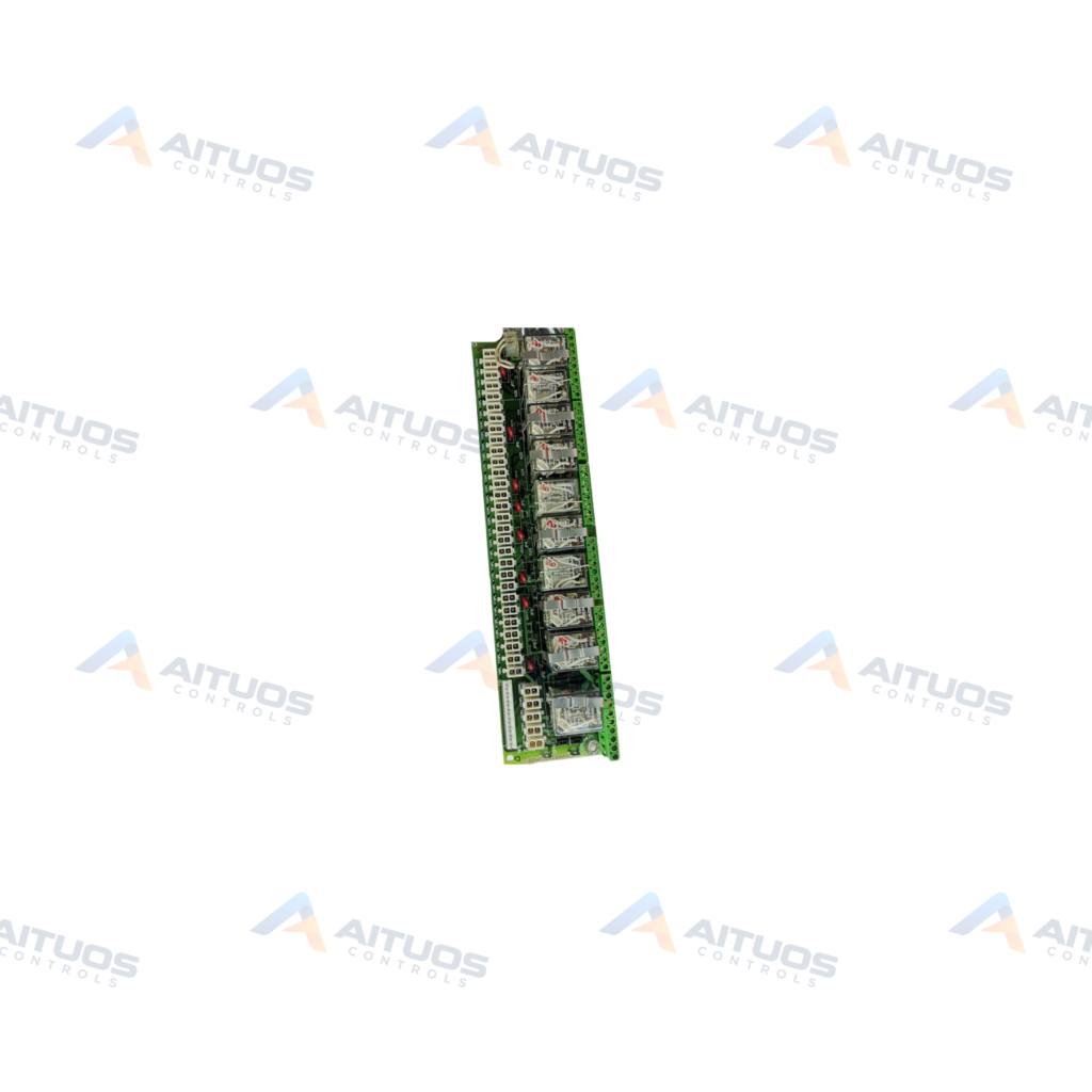
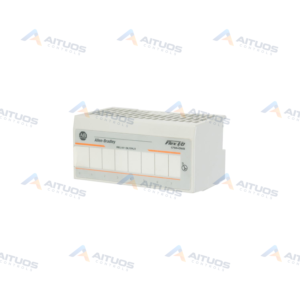
The General Electric DS200RTBAG3AEB is a Mark V Relay Terminal Board designed for drive cabinets. This optional circuit board provides signal routing and relay switching within turbine and automated drive systems. Factory-printed nomenclature labels identify each onboard circuit path clearly across the assembly. It integrates fifty-two terminal connection points to manage remote or direct pilot signal inputs effectively.
The assembly incorporates dedicated relays with individual state indicator lamps and dual form C contacts. Each relay also connects to a single hardware configuration jumper for customizable operational settings. These indicator lamps glow to signal energized relay status during active system operation. The board carries an A-rated functional revision, an E-rated functional revision, and a B-rated artwork configuration revision.
TECHNICAL DATA
Technical Specifications
| Parameter | Specification |
|---|
| Instruction Manual | GEI-100167 |
|---|
| PCB Coating | Normal Coating |
|---|
| Mark V Series Grouping | Group 3 |
|---|
TECHNICAL INFORMATION
Features
- Fifty-two terminal points for wiring drive control signals and relay operations
- Relays equipped with two form C contacts and individual state indicator lamps
- Single hardware configuration jumper attached to each onboard relay
- Onboard state indicator lamps illuminate to verify energized relay status
- Factory-printed nomenclature labels designating circuit components across the board
TECHNICAL INFORMATION
Applications
- General Electric Mark V turbine control system drive cabinets
- Industrial drive relay signal interfacing and excitation control assemblies
TECHNICAL INFORMATION
Connections / Interfaces
- Fifty-two terminal wire connection points for control signals and drive interface wiring
- Hardware configuration jumpers for individual relay circuit customization
TECHNICAL INFORMATION
Installation Guidelines
- Disconnect all incoming electrical power to the drive cabinet before servicing the board.
- Wait at least five seconds after power removal for stored electrical current to dissipate.
- Test all board components and adjacent equipment for residual voltage before physical handling.
- Relays may retain electrical charge for several minutes after system power is completely disconnected.
TECHNICAL INFORMATION
Configuration Guidelines
- Adjust the dedicated hardware jumper assigned to each relay to set functional behavior.
- Access diagnostic utilities through the drive keypad control panel to confirm relay setup parameters.
- Download diagnostic operational reports to an external computer for verification and offline record keeping.
TECHNICAL INFORMATION
Compatibility
- General Electric Mark V drive control system enclosures and excitation frameworks
COMPATIBILITY
Compatibility & Replacement
COMPATIBLE MODELSGeneral Electric Mark V drive control system enclosures and excitation frameworks
Verify compatibility against the exact Part Number, revision and manufacturer documentation before ordering.
PART VERIFICATION
Before You Order
Industrial automation parts can share similar model names, suffixes and revisions. Confirm the complete manufacturer Part Number before purchase.
01Check Part NumberMatch the complete ordering code on the existing unit.
02Confirm RevisionCheck suffix, hardware or firmware when applicable.
03Send a Label PhotoWe can review a clear label photo when identification is uncertain.
ORDERING PROCESS
From RFQ to Dispatch
1Submit Part Number2Verify Product Identity3Confirm Stock & Condition4Issue Quotation5Dispatch & Tracking
PRODUCT FAQ
Frequently Asked Questions
What is the primary function of the GE DS200RTBAG3AEB board?
The board operates as an optional relay terminal card within General Electric Mark V drive cabinets. It routes control signals and switches relays using fifty-two wiring terminal points.
How are individual relay states monitored on the DS200RTBAG3AEB?
Each relay features a dedicated indicator lamp on the circuit board. The lamp glows when the relay coil is energized.
What safety precautions are necessary before touching the DS200RTBAG3AEB?
Isolate all system electrical power completely before maintenance. Wait at least five seconds and test all circuits to ensure stored electrical energy has dissipated.
How can an engineer access onboard diagnostic data for this board?
Diagnostic reports are accessible directly from the drive keypad panel. Technicians can also transfer the report to a laptop to inspect drive configuration settings.