PRODUCT INFORMATION
Product Overview
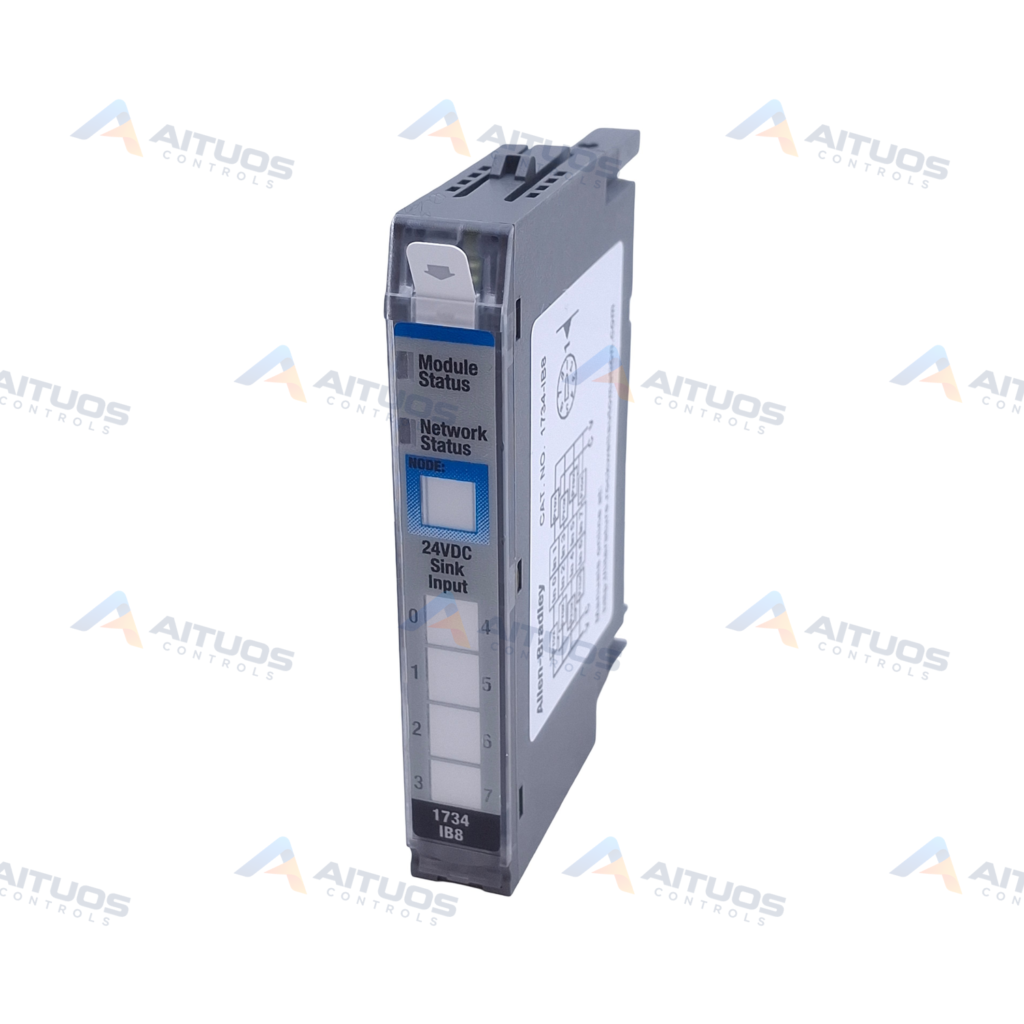
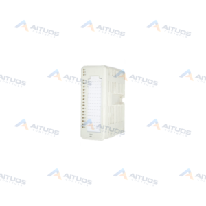
The Allen-Bradley 1734-IB8 POINT I/O Digital Input Module provides eight sinking DC input channels for industrial automation control. This open-style module operates at 24V DC nominal field power with an operational range of 10 to 28.8V DC. Each input channel draws 4 mA nominal current at 24V DC and connects directly to DC proximity sensors.
The unit mounts onto compatible POINT I/O wiring base assemblies using mechanical keyswitch position 1. It draws up to 75 mA of POINTBus backplane current at 5V DC. The module produces one byte of channel data across the backplane network and consumes zero bytes of scanner data.
TECHNICAL DATA
Technical Specifications
| Parameter | Specification |
|---|
| Manufacturer | Allen Bradley |
|---|
| Product Type | POINT I/O Input Module |
|---|
| Product Line | Point I/O 1734 |
|---|
| Part Number | 1734-IB8 |
|---|
| Weight | 0.56 lbs (0.26 kg) |
|---|
| UPC | 10612598308573 |
|---|
| Number of Inputs | 8 Sinking Inputs |
|---|
| Nominal On-State Voltage Rating | 24 Volts DC |
|---|
| On-State Voltage Range | 10 to 28.8 Volts DC |
|---|
| Nominal On-State Current Rating | 4 Milliamps at 24 Volts DC |
|---|
| On-State Current Range | 2 Milliamps to 5 Milliamps |
|---|
| Maximum Off-State Voltage Rating | 5 Volts DC |
|---|
| Minimum Off-State Current Rating | 1.5 Milliamps |
|---|
| Maximum POINTBus Current Rating | 75 Milliamps at 5 Volts DC |
|---|
| Isolation Voltage Rating | 50 Volts (Continuous) |
|---|
| Maximum Power Dissipation Rating | 1.6 Watts at 28.8 Volts DC |
|---|
| Maximum Thermal Dissipation Rating | 5.5 BTU/hr at 28.8 Volts DC |
|---|
| Enclosure Type | Open-Style |
|---|
| Inputs | 8 |
|---|
| Grouping | 1 group of 8 |
|---|
| Input style | Sinking DC |
|---|
| On-state voltage | 10–28.8 VDC; 24 VDC nominal |
|---|
| Off-state voltage maximum | 5 VDC |
|---|
| On-state current | 2–5 mA; 4 mA nominal at 24 VDC |
|---|
| Input impedance | 3.6 kohm nominal; 4.7 kohm maximum |
|---|
| Off-to-on filter | 0.5 ms hardware plus 0–63 ms user-selectable |
|---|
| On-to-off filter | 0.5 ms hardware plus 0–63 ms user-selectable |
|---|
| Produced data | 1 byte, I0–I7; no consumed data |
|---|
| PointBus current maximum | 75 mA at 5 VDC |
|---|
| Power dissipation maximum | 1.6 W at 28.8 VDC |
|---|
| Thermal dissipation maximum | 5.5 BTU/h at 28.8 VDC |
|---|
| Isolation voltage | 50 V continuous, reinforced insulation |
|---|
| Isolation test | 2500 VDC for 60 s, field side to system |
|---|
| Field power | 24 VDC nominal; 10–28.8 VDC |
|---|
| Dimensions | 56.6 × 12.1 × 77.5 mm |
|---|
| Approximate weight | 32.3 g |
|---|
| Enclosure | Open style |
|---|
| Operating temperature | -20 to +55 °C |
|---|
TECHNICAL INFORMATION
Features
- Provides eight sinking 24V DC input channels organized into a single electrical group.
- Features hardware input filtering of 0.5 ms plus software-selectable delays from 0 to 63 ms.
- Supplies reinforced insulation rated at 50V continuous with a 2500V DC test withstand rating.
- Incorporates eight yellow logic-side indicators for input channel status verification.
- Includes dedicated bicolor status indicators for module operational state and network communication health.
TECHNICAL INFORMATION
Connections / Interfaces
- Terminals 0 through 7 connect field input signals for input channels 0 through 7.
- Field power and common connections require external terminal blocks or power distribution expansion modules.
- Accommodates direct wiring connections for standard 2-wire and 3-wire DC proximity switches.
- Transmits one byte of produced data representing the active states of input channels 0 through 7.
TECHNICAL INFORMATION
Installation Guidelines
- Rotate the keyswitch on the wiring base assembly to position 1 before mounting the module.
- Mount the module onto a compatible 1734-TB, 1734-TBS, 1734-TOP, or 1734-TOPS base assembly.
- Tighten terminal base wiring screws to a torque of 0.8 N•m (7 lb•in).
- Disconnect backplane power or confirm the area is nonhazardous before inserting or removing the module.
TECHNICAL INFORMATION
Configuration Guidelines
- Configure input filter delays between 0 and 63 ms in the controller configuration software.
- Verify that the module status indicator displays solid green to confirm normal operation.
- Map the single produced byte into processor memory to read channel states I0 through I7.
TECHNICAL INFORMATION
Compatibility
- Mounts onto 1734-TB, 1734-TBS, 1734-TOP, and 1734-TOPS terminal base assemblies.
- Connects across POINT I/O backplane structures managed by compatible POINT I/O communication adapters.
- Accepts field power distribution from 1734-FPD and 1734-EP24DC power feed units.
TECHNICAL INFORMATION
Compliance and Certifications
- c-UL-us Listed for Class I Division 2 Groups A, B, C, and D Hazardous Locations
- European Union 2014/30/EU EMC Directive and UK Statutory Instrument 2016 No. 1091 compliant
- ATEX and IECEx certified under protection code II 3 G Ex ec IIC T4 Gc
- RoHS compliant under European Union 2011/65/EU and EN IEC 63000 standards
TECHNICAL RESOURCES
Documentation
COMPATIBILITY
Compatibility & Replacement
COMPATIBLE MODELSMounts onto 1734-TB, 1734-TBS, 1734-TOP, and 1734-TOPS terminal base assemblies. Connects across POINT I/O backplane structures managed by compatible POINT I/O communication adapters. Accepts field power distribution from 1734-FPD and 1734-EP24DC power feed units.
Verify compatibility against the exact Part Number, revision and manufacturer documentation before ordering.
PART VERIFICATION
Before You Order
Industrial automation parts can share similar model names, suffixes and revisions. Confirm the complete manufacturer Part Number before purchase.
01Check Part NumberMatch the complete ordering code on the existing unit.
02Confirm RevisionCheck suffix, hardware or firmware when applicable.
03Send a Label PhotoWe can review a clear label photo when identification is uncertain.
ORDERING PROCESS
From RFQ to Dispatch
1Submit Part Number2Verify Product Identity3Confirm Stock & Condition4Issue Quotation5Dispatch & Tracking
PRODUCT FAQ
Frequently Asked Questions
What input configuration is used on the 1734-IB8 module?
The 1734-IB8 provides eight sinking DC inputs operating at 24V DC nominal voltage.
Which wiring base assemblies can be used with the 1734-IB8?
It installs into 1734-TB, 1734-TBS, 1734-TOP, or 1734-TOPS terminal base assemblies.
What keyswitch setting does the 1734-IB8 require?
Set the mechanical keyswitch on the terminal base to position 1 before insertion.
How much backplane current does the 1734-IB8 draw?
The module draws a maximum of 75 mA at 5V DC from the POINTBus.