PRODUCT INFORMATION
Product Overview
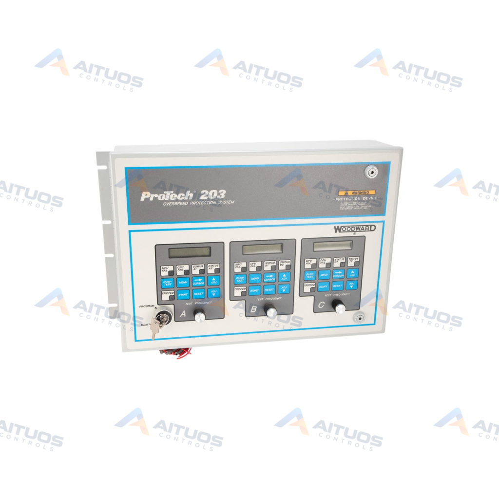
The Woodward 9907-147 ProTech 203 Overspeed Protection System monitors prime mover rotational speed using magnetic pickups. This de-energize-to-trip assembly incorporates three independent speed-sensing units arranged in a two-out-of-three voting configuration. A trip activates only when at least two units detect an overspeed condition. The system detects input frequencies ranging from 100 Hz to 32 kHz across monitoring circuits.
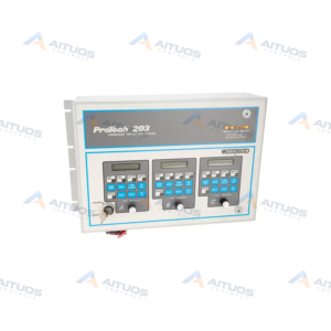
Each speed-sensing unit features a dedicated operator interface containing a two-line sixteen-character LCD screen. Individual interfaces also integrate a touchpad, a potentiometer, status LEDs, and a discrete alarm output. A centralized key switch links all three units to switch between MONITOR mode and PROGRAM mode. This interlock mechanism secures configuration parameters against unauthorized adjustments during normal operation.
TECHNICAL DATA
Technical Specifications
| Parameter | Specification |
|---|
| Dimensions | W482.6mm x H310.4mm x D142.7mm |
|---|
| Display Operating Temperature | –15 to +60 °C |
|---|
| Features | Key Lock |
|---|
| Input Voltage | 24 Vdc |
|---|
| Keypad/Display | 3 LCDS | 2 Lines of 16 Characters |
|---|
| Operating Temperature | –25 to +60 °C |
|---|
| Weight | Less than 17 lbs |
|---|
TECHNICAL INFORMATION
Features
- Two-out-of-three voting logic across three independent speed-sensing channels
- De-energize-to-trip architecture for prime mover overspeed shutdown protection
- Speed-sensing frequency range spanning 100 Hz to 32 kHz
- Configurable trip-point frequency range from 250 Hz to 25 kHz
- Three dedicated operator interfaces with two-line by sixteen-character LCD displays
- Shared key lock switch to toggle between MONITOR and PROGRAM modes
TECHNICAL INFORMATION
Applications
- Prime mover overspeed detection and shutdown protection
- Turbomachinery monitoring using magnetic pickup speed inputs
TECHNICAL INFORMATION
Connections / Interfaces
- Magnetic pickup signal inputs for prime mover speed monitoring
- Dedicated discrete alarm outputs on each speed-sensing unit interface
TECHNICAL INFORMATION
Installation Guidelines
- Mount the unit in an environment with adequate ventilation for cooling.
- Ensure sufficient clearance around the enclosure for servicing and maintenance.
- Locate the equipment away from direct sunlight exposure.
- Isolate the unit from high-current conductors and high-voltage electrical devices.
- Protect the device against excessive vibration, moisture, and electromagnetic interference.
TECHNICAL INFORMATION
Configuration Guidelines
- Trip set points must be programmed identically across all three individual units.
- Use the dedicated touchpad and display interface on each unit to set parameters.
- Turn the master key switch to PROGRAM mode before attempting setting alterations.
- Return the key switch to MONITOR mode to prevent unauthorized parameter adjustments.
PART VERIFICATION
Before You Order
Industrial automation parts can share similar model names, suffixes and revisions. Confirm the complete manufacturer Part Number before purchase.
01Check Part NumberMatch the complete ordering code on the existing unit.
02Confirm RevisionCheck suffix, hardware or firmware when applicable.
03Send a Label PhotoWe can review a clear label photo when identification is uncertain.
ORDERING PROCESS
From RFQ to Dispatch
1Submit Part Number2Verify Product Identity3Confirm Stock & Condition4Issue Quotation5Dispatch & Tracking
PRODUCT FAQ
Frequently Asked Questions
What voting architecture does the Woodward 9907-147 use?
The Woodward 9907-147 uses a two-out-of-three voting architecture. At least two speed units must detect overspeed to trip.
What is the speed detection frequency range of this system?
The sensing circuit operates from 100 Hz to 32 kHz. Trip setpoints configure between 250 Hz and 25 kHz.
How are configuration parameters protected from unauthorized edits?
A central key lock switch controls access. Switching from MONITOR to PROGRAM mode enables parameter entry across units.