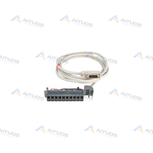
PRODUCT INFORMATION
Product Overview
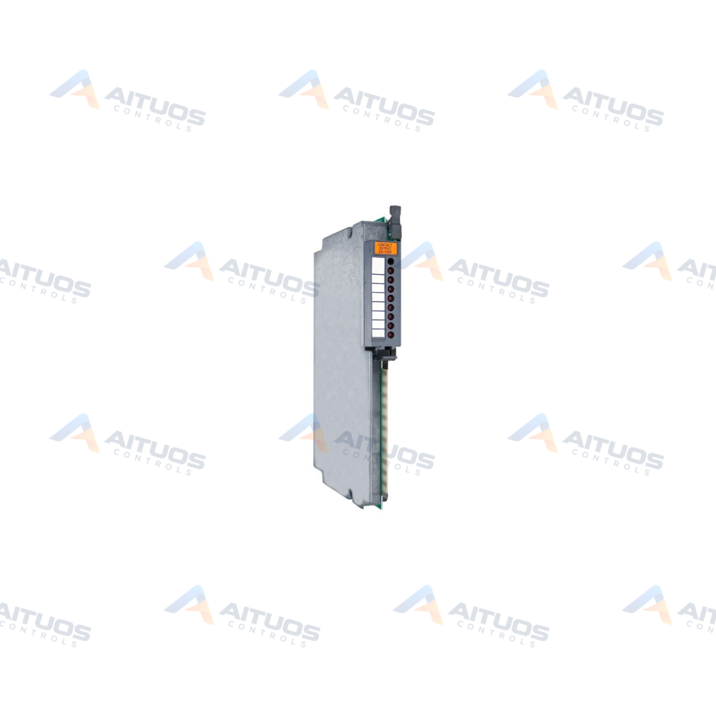
The Allen-Bradley 1771-OW is a PLC-5 selectable contact module. This unit provides eight relay output channels arranged across four isolated groups. Each two-channel group includes an individual common terminal for separate circuits. Individual channels support field configuration as normally open or normally closed contacts. The factory default setting for every channel contact is normally open.
Internal electrical isolation separates module logic circuitry from field contact outputs. The module operates across 24 to 138 Volts AC or 24 to 125 Volts DC. Each output channel conducts a maximum continuous flow of 1.0 Ampere current. All eight relay output channels can activate simultaneously under full operational load. Backplane current draw reaches a maximum of 700 milliamperes. The module mounts into any standard 1771 chassis slot except the leftmost processor position.
TECHNICAL DATA
Technical Specifications
| Parameter | Specification |
|---|
| Category | PLCs |
|---|
| Product Line | PLC 5 |
|---|
| GTIN | 10662468205914 |
|---|
| Weight | 2.44 lbs (1.11 kg) |
|---|
| Module Type | Selectable relay output module |
|---|
| No. of Inputs | Eight (8) relay channels |
|---|
| No. of groups | Four (4) |
|---|
| Channels per group | Two (2) |
|---|
| Default configuration | Normally Open (N.O.) |
|---|
| Operating Voltage Range | 24 – 138VAC RMS; 24 – 125VDC |
|---|
| Output current rating per channel | 1.0 A |
|---|
| Power Dissipation | 3.3-3.7 Watts |
|---|
| Thermal Dissipation | 11.3-12.7 BTU/hr |
|---|
| Compatible chassis | 1771 I/O chassis |
|---|
| Keying | Between 6 and 8; Between 16 and 18 |
|---|
| Field Wiring Arm | Cat. No. 1771-WD |
|---|
| Wiring Arm Screw Torque | 7-9 inch-pounds |
|---|
| Number of Outputs | 8 (4 Sets of 2) Ouputs |
|---|
| AC Operating Voltage | 24-138 Volts |
|---|
| DC Operating Voltage | 24-235 Volts |
|---|
| Backplane Current | 700 Miliamperes |
|---|
| Wiring Arm | 1771-WH |
|---|
| Coating | Conformal Coat |
|---|
| Typical AC Signal Delay (Off) | 45 (+/- 15) ms |
|---|
| Typical DC Signal Delay (Off) | 50 ms |
|---|
| Mounting | Rack Mountable |
|---|
TECHNICAL INFORMATION
Features
- Eight selectable contact outputs grouped into four isolated pairs.
- Jumper selection between normally open and normally closed contact states.
- Internal electrical isolation between module logic circuitry and field contacts.
- Simultaneous operation across all eight relay output channels.
- Maximum continuous current capacity of 1.0 Ampere per channel.
- Conformal coating protection for industrial operating environments.
TECHNICAL INFORMATION
Applications
- Resistive AC load switching within 24 to 138 Volts AC.
- Direct DC load switching within 24 to 125 Volts DC.
- Isolated circuit switching requiring separate commons across channel pairs.
TECHNICAL INFORMATION
Connections / Interfaces
- Four isolated pairs of relay contacts with individual common connections.
- Connection to external field circuits through removable 1771-WD or 1771-WH wiring arms.
- Chassis backplane connector for logic power and bus signals.
TECHNICAL INFORMATION
Installation Guidelines
- Insert the module into any available 1771 chassis slot except the leftmost slot.
- The leftmost chassis slot is reserved strictly for processor or adapter modules.
- Position plastic keying bands between pins 6 and 8, and pins 16 and 18.
- Connect external field wiring using a 1771-WD or 1771-WH field wiring arm.
- Use stranded wire up to 14 AWG with 3/64-inch maximum insulation thickness.
- Tighten field wiring arm terminal screws to 7 to 9 inch-pounds.
- Keep interconnect wiring runs within 1000 feet or 304.8 meters.
TECHNICAL INFORMATION
Configuration Guidelines
- Output relay contacts are factory pre-set to normally open operation.
- Reposition individual channel jumpers to set normally closed operation.
- Connected AC loads must maintain a power factor of 1.0.
TECHNICAL INFORMATION
Compatibility
- Compatible with Allen-Bradley 1771 I/O chassis assemblies.
- Interfaces with 1771-WD and 1771-WH field wiring arms.
TECHNICAL RESOURCES
Documentation
COMPATIBILITY
Compatibility & Replacement
COMPATIBLE MODELSCompatible with Allen-Bradley 1771 I/O chassis assemblies. Interfaces with 1771-WD and 1771-WH field wiring arms.
Verify compatibility against the exact Part Number, revision and manufacturer documentation before ordering.
PART VERIFICATION
Before You Order
Industrial automation parts can share similar model names, suffixes and revisions. Confirm the complete manufacturer Part Number before purchase.
01Check Part NumberMatch the complete ordering code on the existing unit.
02Confirm RevisionCheck suffix, hardware or firmware when applicable.
03Send a Label PhotoWe can review a clear label photo when identification is uncertain.
ORDERING PROCESS
From RFQ to Dispatch
1Submit Part Number2Verify Product Identity3Confirm Stock & Condition4Issue Quotation5Dispatch & Tracking
PRODUCT FAQ
Frequently Asked Questions
What is the default contact configuration for the Allen-Bradley 1771-OW?
Every relay channel is factory configured as normally open. Users can reposition internal jumpers to select normally closed contact operation.
Which field wiring arm is compatible with the 1771-OW module?
The module connects to field wiring using a 1771-WD or 1771-WH wiring arm. Terminal screws on the wiring arm require 7 to 9 inch-pounds of torque.
Can all eight relay channels operate simultaneously?
Yes, all eight relay channels can be activated at the same time. The module draws up to 700 milliamperes from the backplane supply when fully energized.
What is the market reference price for the 1771-OW?
Observed market prices range from 119.00 USD to 328.00 USD. These figures represent indicative market reference pricing only and are not a final quotation. Final pricing depends on item condition, testing, and current inventory levels.